Methods and systems for active wing and lift surface control using integrated aeroelasticity measurements

a technology of aeroelasticity and measurement system, applied in the direction of process and machine control, instruments, navigation instruments, etc., can solve the problems of limited improvement, lack of integration of aeroelasticity measurement system, and limited improvement, so as to increase aircraft performance

Active Publication Date: 2010-03-25
THE BOEING CO
View PDF23 Cites 22 Cited by
  • Summary
  • Abstract
  • Description
  • Claims
  • Application Information

AI Technical Summary

Benefits of technology

[0008]In another aspect, a method for increasing aircraft performance is provided. The method includes receiving at least one of real-time wing twist measurements and real time measurements of aircraft body bending from an aeroelasticity measurement system, calculating at least one of a desired flight control surface position and a desired lift surface position based on the received measurements and current flight conditions, and operating a plurality of actuators mechanically coupled to the aircraft to achieve the at least one desired flight control surface position and desired lift surface position.

Problems solved by technology

There have been experimental aircraft and military aircraft that allow active wing control, however, these applications do not utilize an integrated aeroelasticity measurement system.
However, such improvements are limited, due to the fixed nature of flight testing and computer simulations.
While the method provides a potential improvement, the improvements are limited due to a finite set of data points in the predicted tables, and by the limited effectiveness of using flight control surfaces to lower wing drag.
That is, use of flight control surfaces to shape the wing for lower drag is limited because these shape changes also induce wake vortexes and changes to wing camber that tend, after a point, to cancel the improvements in drag.

Method used


Image

  • Methods and systems for active wing and lift surface control using integrated aeroelasticity measurements
  • Methods and systems for active wing and lift surface control using integrated aeroelasticity measurements
  • Methods and systems for active wing and lift surface control using integrated aeroelasticity measurements

Examples


Embodiment Construction

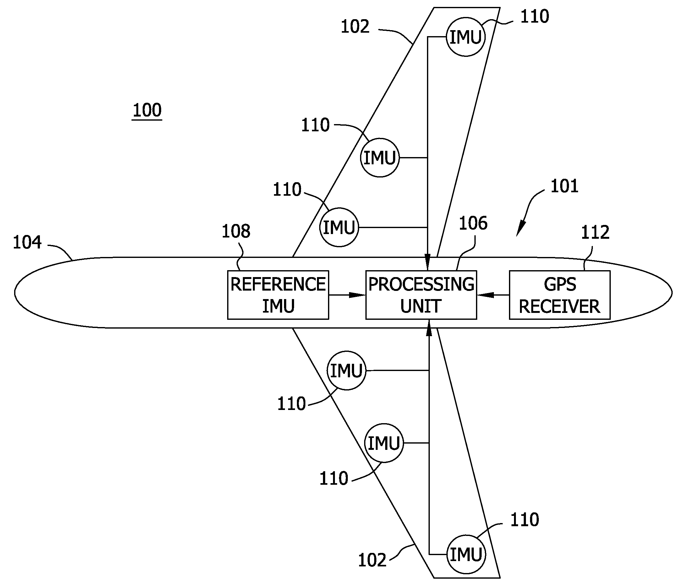
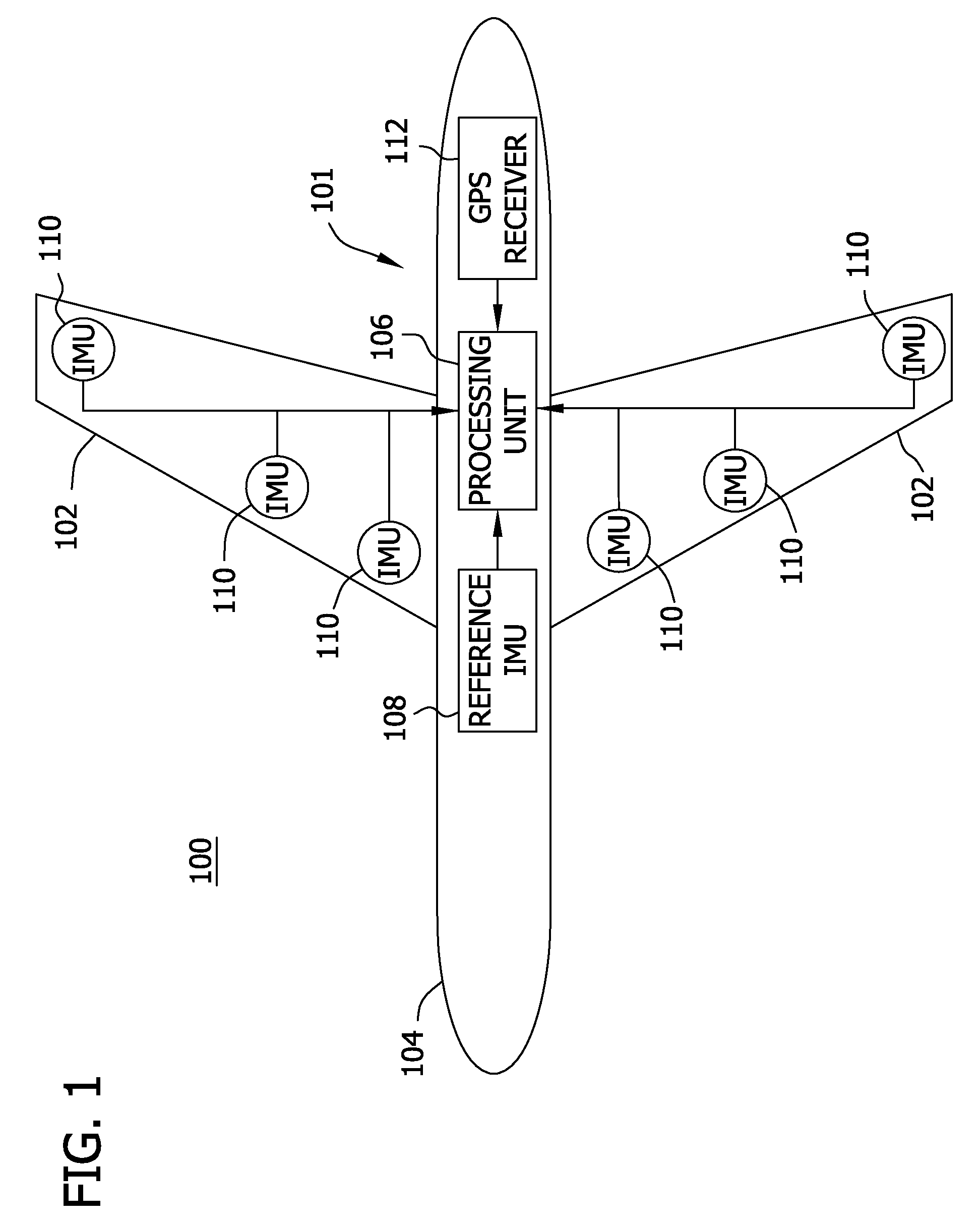
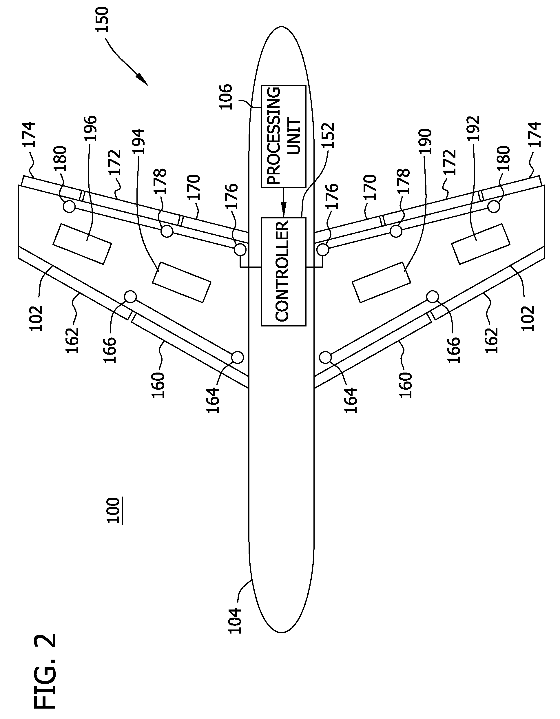
[0014]A typical aircraft has lift surfaces and control surfaces. The lift surfaces (wing, canard, fuselage and the like) provide lift as a function of engine thrust, while the control surfaces (ailerons, flaps, rudder and the like) may be moved by means of actuators to control the aircraft flight path, commonly called flight control. The description herein introduces the concept of actuators that may be used not for flight control in the traditional sense, but to achieve a lower drag by flexing lift surfaces, typically the wing, to a more desirable (e.g., fuel efficient) shape. Thus a distinction is made between flight control and lift surface control wherein existing flight control surfaces may be used to achieve a desired lift surface shape but also actuators in a lift surface designed for active shape control may be used to the same end. In practice existing flight control surfaces can be used to achieve control of lift surface shape (to twist a wing, for example) but this is les...


PUM


Abstract

An active wing and lift surface control system for an aircraft is described. The wing and lift surface control system includes an aeroelasticity measurement system configured to provide at least one of real time wing twist measurements and real time measurements of aircraft body bending, at least one actuator mechanically coupled to a control surface of the aircraft, and a control system communicatively coupled to the aeroelasticity measurement system and to the at least one actuator. The control system is operable to receive the measurements from the aeroelasticity measurement system and generate control signals, based on the real time measurements, to operate the at least one actuator to adjust a drag associated with one or more of the wing and the aircraft body.

Description

BACKGROUND[0001]The field of the disclosure relates generally to aircraft wing and lift surface control, and more specifically, to methods and systems for active lift surface control using integrated aeroelasticity measurements.[0002]Expectations are that future aircraft designs will face increasing pressure to improve fuel efficiency and performance. One effective fuel efficiency technique is accomplished through measurement of wing twist for various phases of an aircraft flight. Specifically, wing twist is measured, and the data used to produce a reduction in drag through design of a more efficient wing.[0003]To that end, integrated systems for measuring wing twist have been developed for flight test purposes and are referred to herein as integrated aeroelasticity measurement systems. Current practice employs the integrated aeroelasticity measurement system in flight testing, using it to measure actual twist and bending of the airframe for selected flight conditions (aircraft spee...

Claims


Application Information

Patent Timeline
Patent Type & Authority Applications(United States)
IPC IPC(8): G01C21/00G05D1/04
CPCG01C21/165G01M5/0041G01M5/0016
Inventor HINNANT, JR., HARRIS O.BLACK, DAVID J.BREKKE, DARIN W.CASTELHICCIO, MARK A.DICKERSON, MATT R.
Owner THE BOEING CO
Why Eureka
Try Eureka