
Direct Current Power Distribution and Fault Protection

a technology of direct current and power distribution system, applied in the direction of dc-ac conversion without reversal, emergency protective circuit arrangement, dc network circuit arrangement, etc., can solve the problems of power among several loads, disadvantages of hardware complexity and duplication, seat power converters often contain complex circuitry, etc., to reduce the hardware requirements of complex systems, safe and effective power distribution system, and weight reduction

Inactive Publication Date: 2017-07-20
ASTRONICS ADVANCED ELECTRONICS SYST
View PDF10 Cites 9 Cited by
  • Summary
  • Abstract
  • Description
  • Claims
  • Application Information

AI Technical Summary

Benefits of technology

The patent provides a power distribution system that uses DC power, which is safer and more efficient. This system reduces the need for power processing locally, which saves money and weight in complex systems. This makes it easier for aircraft operators to improve performance and save money over the life span of the aircraft.

Problems solved by technology

The distribution of power among several loads presents certain challenges.
This can be particularly true in environments where there is a limited amount of available power, but where hardware complexity and duplication are disadvantageous.
Thus, the seat power converters often contain complex circuitry, such as energy storage and filtering devices, to adequately meet these requirements.
In addition to the disadvantages inherent in complex circuitry, undesirable heat is generated at the point of conversion by processing power locally at the passengers' seats.

Method used


Image

  • Direct Current Power Distribution and Fault Protection
  • Direct Current Power Distribution and Fault Protection
  • Direct Current Power Distribution and Fault Protection

Examples


Embodiment Construction

[0016]In a certain embodiments, 56 VDC in total is distributed from a HVDCU to control units by passing +28 VDC across a positive distribution rail and −28 VDC across a negative distribution rail. In such an embodiment, it will be understood by those of ordinary skill in the art that the provided voltages are ideal and that minor fluctuations in the voltages can be consistent with those experienced by similar distribution systems without departing from the disclosed subject matter. For instance, in an embodiment the tolerance may be + / −7%, which allows the system to remain below a 60 VDC upper limit. In another embodiment, the tolerance may be + / −5% so as to meet power quality standards of 5-10%.

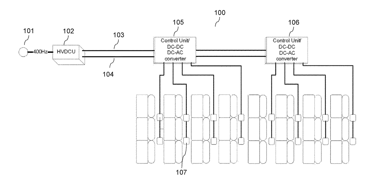
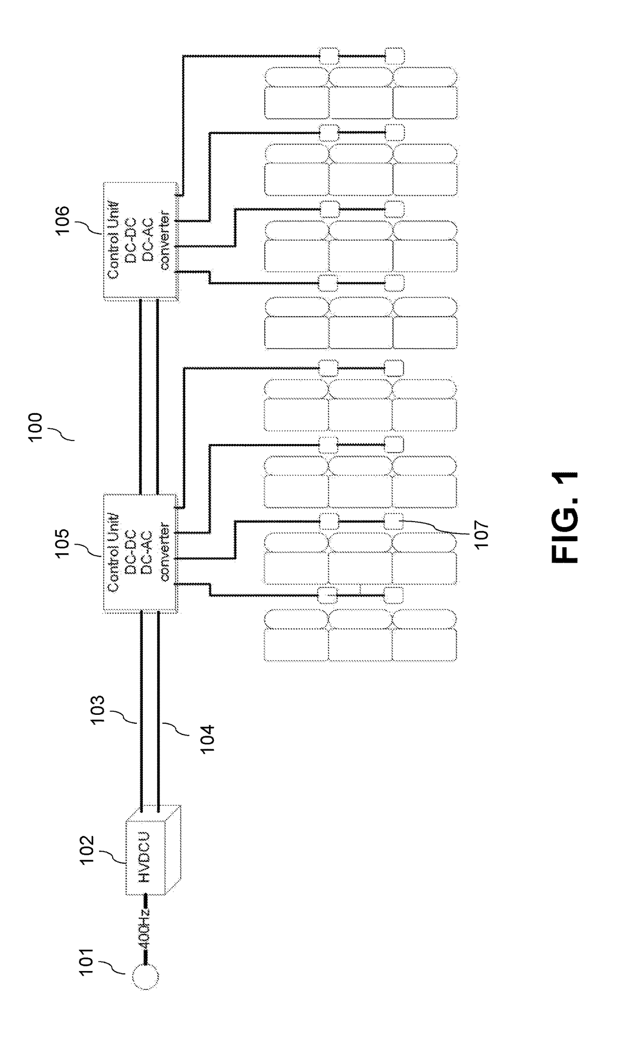
[0017]FIG. 1 is a schematic illustration of the 56 VDC embodiment. Aircraft power distribution and management system 100 has power source 101 that provides high-frequency AC input power to HVDCU 102. HVDCU 102 includes a PFC unit (not shown) and a DC-DC converter (not shown). The PFC unit co...


PUM


Abstract

A power distribution system including a high-voltage direct current unit (HVDCU) configured to receive an amount of high-frequency alternating current (AC) input power from a power source and convert the input power into DC power, a negative voltage distribution rail and a positive voltage distribution rail that are together configured to supply the high-voltage DC power to at least one control unit (CU) electrically disposed between the negative voltage distribution rail and the positive voltage distribution rail and the CU being configured to convert the DC power into output power compatible with at least one load and supply the output power to the loads associated with it.

Description

CROSS REFERENCE TO RELATED APPLICATION[0001]The present application is a Continuation-in-Part of U.S. patent application Ser. No. 14 / 514,617, entitled “High-Voltage Direct Current Power Distribution and Fault Protection” and filed Oct. 15, 2014. U.S. Ser. No. 14 / 514,617 is a Continuation-in-Part of U.S. patent application Ser. No. 14 / 273,139, entitled “Power Distribution System for Low-Frequency AC Outlets” and filed May 8, 2014. The disclosures of U.S. Ser. No. 14 / 514,617 and U.S. Ser. No. 14 / 273,139 are hereby incorporated by reference herein in their entireties.FIELD OF THE DISCLOSURE[0002]The subject matter of the present disclosure generally relates to power distribution systems, and more particularly relates to distribution of high-voltage direct current.BACKGROUND OF THE DISCLOSURE[0003]The distribution of power among several loads presents certain challenges. This can be particularly true in environments where there is a limited amount of available power, but where hardware ...

Claims


Application Information

Patent Timeline
Patent Type & Authority Applications(United States)
IPC IPC(8): H02J1/00H02H3/16H02M7/44H02M7/04H02M3/04
CPCH02J1/00H02M7/04H02H3/162H02M7/44H02M3/04H02M1/4216H02J4/00H02H3/10H02H3/087H02H3/32H02J2310/44Y02B70/10
Inventor JOUPER, JEFFREY A.FIFIELD, JOHN
Owner ASTRONICS ADVANCED ELECTRONICS SYST
Learn More