Radio wave propagation characteristic estimation apparatus and computer program

a estimation apparatus technology, applied in the field of radio wave propagation characteristic estimation apparatus and computer program, can solve the problems of difficult to take into account diffraction waves, take the trouble, and the ray launching method and the imaging method are not properly combined

Inactive Publication Date: 2010-03-25
KDDI CORP
View PDF4 Cites 9 Cited by
  • Summary
  • Abstract
  • Description
  • Claims
  • Application Information

AI Technical Summary

Benefits of technology

[0016]The present invention seeks to solve one or more of the ab

Problems solved by technology

However, it is difficult to take diffraction waves into consideration.
However, in the aforementioned conventional techniques, the ray launching method and the imaging method are not properly combined.
However, it is necessary to take the trouble to select the use of either the ray launching method or the imaging method for every propagation route based on the number of reflections.
This is inefficient.
This is very inefficient.
However, if s

Method used


Image

  • Radio wave propagation characteristic estimation apparatus and computer program
  • Radio wave propagation characteristic estimation apparatus and computer program
  • Radio wave propagation characteristic estimation apparatus and computer program

Examples


Embodiment Construction

[0032]The invention will be now described herein with reference to illustrative embodiments. Those skilled in the art will recognize that many alternative embodiments can be accomplished using the teachings of the present invention and that the invention is not limited to the embodiments illustrated for explanatory purposes.

[0033]Hereunder is a description of embodiments of the present invention with reference to the drawings.

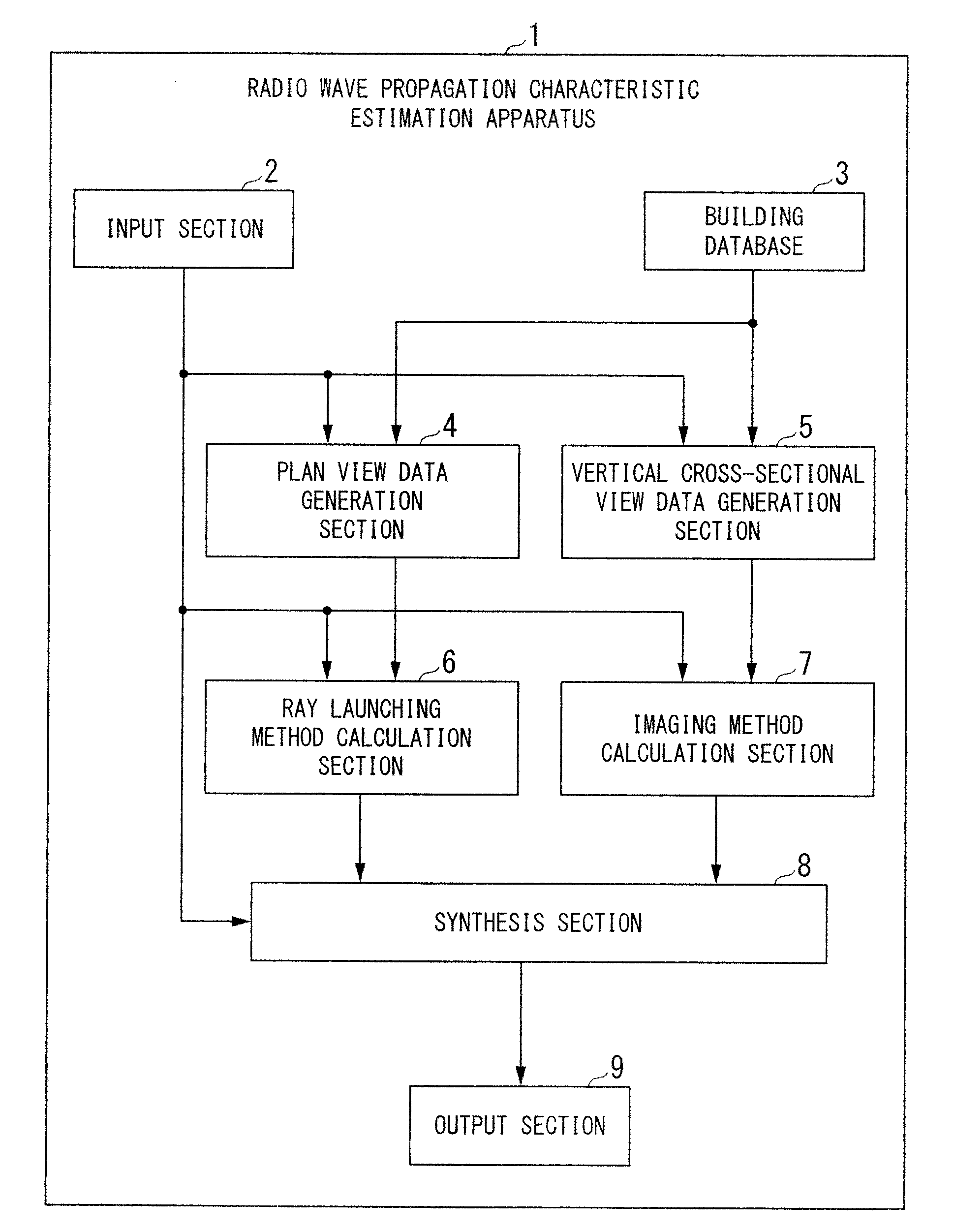
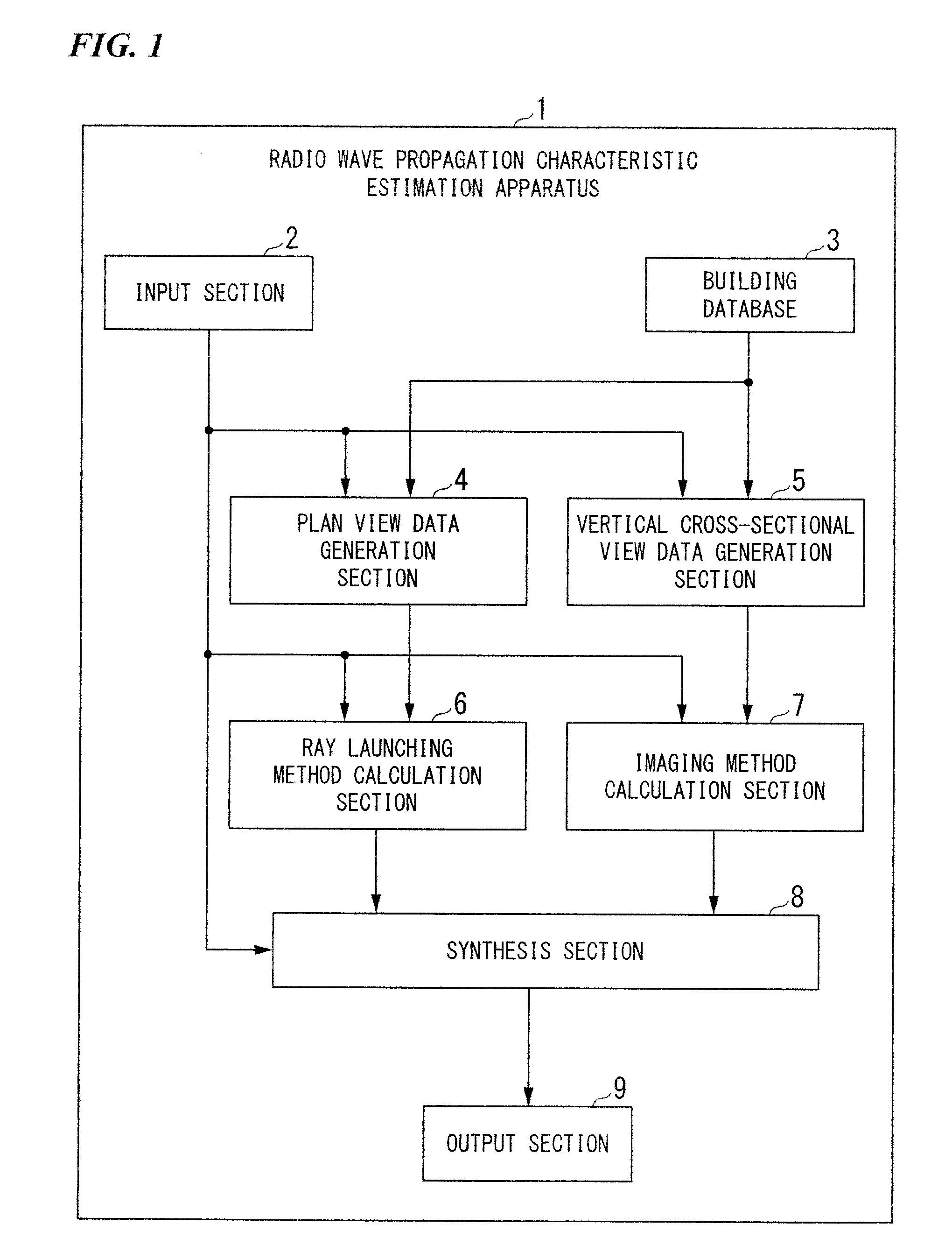
[0034]FIG. 1 is a block diagram showing a configuration of a radio wave propagation characteristic estimation apparatus 1 according to an embodiment of the present invention. In FIG. 1, the radio wave propagation characteristic estimation apparatus 1 includes: an input section 2; a building database 3; a plan view data generation section 4; a vertical cross-sectional view data generation section 5; a ray launching method calculation section 6; an imaging method calculation section 7; a synthesis section 8; and an output section 9.

[0035]The input section 2 is fo...


PUM


Abstract

A radio wave propagation characteristic estimation apparatus includes at least a ray launching method calculation unit, an imaging method calculation unit, and a synthesis unit. The ray launching method calculation unit calculates a first piece of radio wave propagation characteristic estimation data in which a radio wave propagation characteristic from a radio wave transmission point to a building with a radio wave reception point is estimated, using a plan view data. The imaging method calculation unit calculates a second piece of radio wave propagation characteristic estimation data in which a radio wave propagation characteristic from the radio wave transmission point to the building with the radio wave reception point is estimated, using the vertical cross-sectional view data. The synthesis unit calculates pieces of indoor penetration data to the radio wave reception point within the building respectively for the first piece and the second piece, and synthesizes the pieces of indoor penetration data.

Description

BACKGROUND OF THE INVENTION[0001]1. Field of the Invention[0002]The present invention relates to a radio wave propagation characteristic estimation apparatus and a computer program.[0003]Priority is claimed on Japanese Patent Application No. 2008-242516, filed Sep. 22, 2008, the content of which is incorporated herein by reference.[0004]2. Description of Related Art[0005]In a wireless communication system such as a mobile phone network, there are conventionally known a variety of techniques where in order to estimate a communicable region (a service area) of a given base station, a ray tracing method is used to calculate radio wave propagation characteristic estimation data (a trace of a radio wave, a propagation loss, a received signal intensity, and the like) in which a characteristic related to propagation of a radio wave launched from one base station is estimated. The ray tracing method is disclosed in, for example, Non-Patent Document 1, “Hosoya, Yoshio (Ed.), Radiowave Propag...

Claims


Application Information

Patent Timeline
IPC IPC(8): G06G7/62G06F17/50
CPCH04W16/18G06F17/5009G06F30/20
Inventor YONEZAWA, KENYAINOUE, TAKASHI
Owner KDDI CORP
Why Eureka
Try Eureka