
Offset spindle cotton picker bar

a picker bar and spindle technology, applied in the field of picker bars, can solve the problems of increasing the power requirement at the time, increasing the difficulty of maintaining the reliability of the spindle, and increasing the cost of manufacturing, so as to improve the picking efficiency and save the cos

Active Publication Date: 2010-04-01
DEERE & CO
View PDF6 Cites 5 Cited by
  • Summary
  • Abstract
  • Description
  • Claims
  • Application Information

AI Technical Summary

Benefits of technology

[0005]It is therefore an object of the present invention to provide a picker spindle bar with improved picking efficiency compared to conventional spindle bars with inline spindles. It is another object to provide such a spindle bar but which is economical to manufacture and does not require nonconventional complex spindle drives or nonconventional moistener pad and doffer columns.
[0006]It is another object of the present invention to provide an improved picker spindle bar which, compared to conventional spindle bars, improves picking efficiency, provides smoother row unit operation, reduces plugging and provides a more uniform flow of cotton from the spindles into the conveying system. It is a further object to provide such a spindle bar which improves picking efficiency compared to a conventional spindle bar with the same number of spindles.
[0007]A picker spindle bar includes spindles angled relative to each other so the picking ends on a single bar are offset in the direction of picker drum rotation. In an exemplary embodiment, adjacent spindles are angled about the drive shaft axis with the spindle axes intersecting the drive shaft axis. The axes of adjacent spindles are angled about six degrees relative to each other, and the tips of the adjacent spindles are offset on the order of one-half inch (1.27 cm) in the direction of picker drum rotation. The spindle pattern facilitates spacing of the spindles over a range of spacings from 1.625 (4.13 cm) inch to approximately 1.375 inches (3.5 cm).
[0008]Because the spindles are offset angularly about the drive shaft axis and have rotational axes intersecting the drive shaft, a single common drive shaft can be employed and expensive nonconventional drive arrangements can be avoided. By angling the spindles and offsetting the spindle ends, only a fraction of the spindles of a bar initially enter the doffing zone, and the remaining spindles enter shortly thereafter to spread the peak load into two smaller peaks. The magnitude of the doffer and drum peak load spikes are therefore significantly reduced compared to a spindle bar with aligned spindles. The air system loading is also more even since all the cotton from the column of spindles is not entering the air stream at the exact same moment. The row unit and air system run more uniformly with less peak load spiking and plugging compared to row units with conventional aligned spindles.
[0009]The angled spindles also improve picking efficiency in the cotton plant and reduce plugging as a result of the spindle picking end offset. The alternating spindle offset spaces adjacent spindle picking ends fore-and-aft in the plant to more effectively engage the cotton bolls, especially tight immature bolls. The offset also opens the area between spindles for reduced cotton pinching and causes a portion of the spindles to make doffer and moistener pad contact before the remaining portion of the spindles to afford the cotton better opportunity to move into the doffing and cleaning zones without plugging.
[0010]The same or similar manufacture equipment used to manufacture the previously available spindle bars can also be used to manufacture the improved spindle bars. Picking efficiency and smoother row unit operation can be achieved without increasing the number of spindles on each picker bar and without need for special drives or spindle mounting assemblies, thereby minimizing the complexity and cost of the bar.

Problems solved by technology

All the spindles on a spindle bar enter the doffing zone at the same time and cause a power requirement spike at the time of entry.
An excess amount of cotton can get pinched between the aligned spindles and the doffer and cause plugging.
The spacing between the spindle planes and thus the density of the spindles on the picker bar is limited by the spindle support and spindle drive arrangement.
Therefore, increasing the spindle density for increased drum productivity while maintaining the reliability of the spindle, spindle bar and spindle drive has been a continuing source of difficulty.
Such a spindle bar with increased spindle density has been shown to improve picking efficiency but requires a complex and relatively expensive non-conventional spindle drive.

Method used


Image

  • Offset spindle cotton picker bar
  • Offset spindle cotton picker bar
  • Offset spindle cotton picker bar

Examples


Embodiment Construction

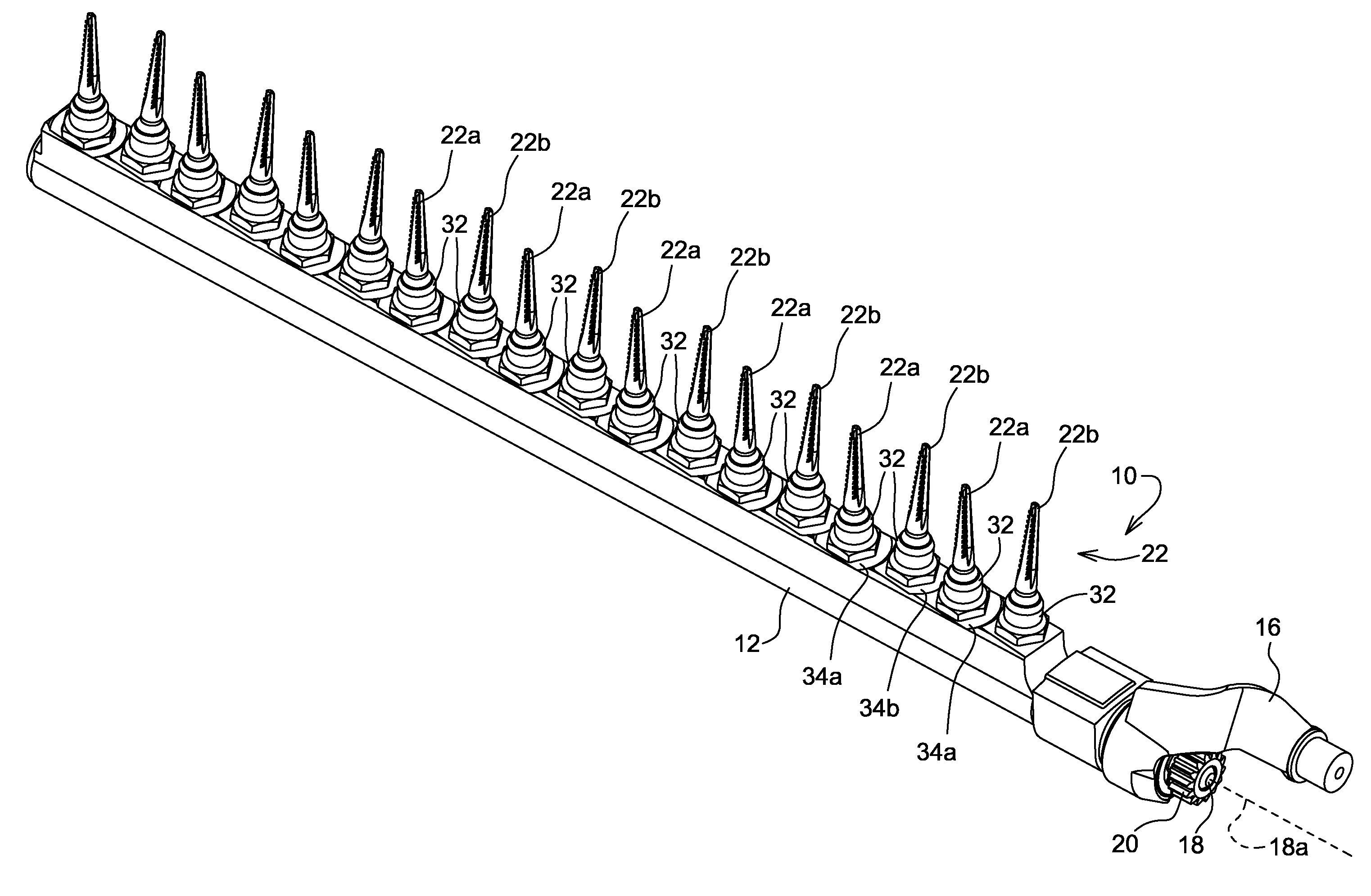
[0015]Referring to FIGS. 1 and 2, therein is shown a portion of a cotton picker row unit 6 having a picker spindle drum 8 with picker spindle bar assemblies 10 adapted for forward movement (F) through rows of cotton plants. A doffer assembly 11 with doffer pads 11a and 11b (FIG. 2) is supported in the row unit adjacent the path of the picker bar assemblies 10. Each picker bar assembly 10 includes a hollow picker bar 12 with an upper end 14 adapted for journaling in the row unit drum head and receiving a cast cam follower arm 16. A spindle drive shaft 18 is rotatably mounted in the hollow picker bar 12 for rotation about an upright axis 18a. A driven gear 20 is fixed to the upper end of the shaft 18 for meshing with a conventional drive gear such as sun gear (not shown).

[0016]The picker bar assembly 10 includes two nonaligned sets 22a and 22b of tapered spindles 22 having axes of rotation 22c and 22d, respectively, slightly inclined to the horizontal so that the planes of the tops of...


PUM


Abstract

A picker spindle bar includes spindles oriented on the bar to offset the spindle picking ends relative to each other. In an exemplary embodiment, adjacent spindle axes are rotated six degrees relative to each other about the upright spindle drive shaft axis so that the picking ends of adjacent spindles are offset and enter the doffing zone at different times to reduce peak loads on the harvester row unit. The angled spindle configurations also space picking ends fore-and-aft in the picking zone and improve harvesting efficiency, especially where green bolls are present. The staggered spindle ends reduces cotton pinching in the picking, doffing and spindle wiping areas to thereby reduce row unit plugging.

Description

FIELD OF THE INVENTION[0001]The present invention relates to spindle type cotton harvesters and, more specifically, to a picker bar for such a harvester.BACKGROUND OF THE INVENTION[0002]Cotton harvesters typically include a row unit structure with picker drums rotatable about upright axes adjacent a row-receiving area of the unit. The drum includes a plurality of upright picker bars having spindles which rotate in contact with cotton plants to remove the cotton. The spindles are aligned vertically in columns, and corresponding spindles on the bars define generally horizontal spindle planes, with a typical drum having eighteen to twenty spindle planes.[0003]Doffers rotate between the spindle planes in contact with the spindles to doff cotton wound on the spindles and direct the cotton towards air door structure for removal from the unit towards a basket or processor. All the spindles on a spindle bar enter the doffing zone at the same time and cause a power requirement spike at the t...

Claims


Application Information

Patent Timeline
IPC IPC(8): A01D46/18
CPCA01D46/18
Inventor GOERING, KEVIN JACOB
Owner DEERE & CO
Learn More