Structures with adaptive cooling

a technology of adaptive cooling and structures, applied in mechanical equipment, machines/engines, light and heating equipment, etc., can solve problems such as local hot spots, and achieve the effect of reducing the effects of hot spots

Active Publication Date: 2010-04-01
RTX CORP
View PDF15 Cites 33 Cited by
  • Summary
  • Abstract
  • Description
  • Claims
  • Application Information

AI Technical Summary

Benefits of technology

[0009]In an exemplary structure, a mounting support includes a coolant aperture for directing a coolant through the support. A liner is mounted to the support, the liner includes a wall having a hot surface facing away from the support and a cold surface contacting the support in an average temperature location. The liner wall deflects away from the support in a hot spot location, forming a chamber between the cold surface and the support. The deflection allows the coolant to impinge on the cold surface of the liner to mitigate the effects of the hot spot.
[0010]In an exemplary method, a coolant is introduced into a coolant aperture in a support and is directed into a channel between the support and a liner without impinging the coolant against the liner in a average temperature location. The liner deflects away from the support to form a chamber between the liner and support in a hot spot location. The coolant impinges against the liner to mitigate the effects of the hot spot.

Problems solved by technology

Unfortunately, the gas path air temperature tend to vary spanwisely and circumferentially around the engine at constant axial locations.
Also, local hot spots can develop in the gas path air due to shifts in aerodynamics, hardware deterioration, cooling passage clogging and other such causes.

Method used


Image

  • Structures with adaptive cooling
  • Structures with adaptive cooling
  • Structures with adaptive cooling

Examples


Embodiment Construction

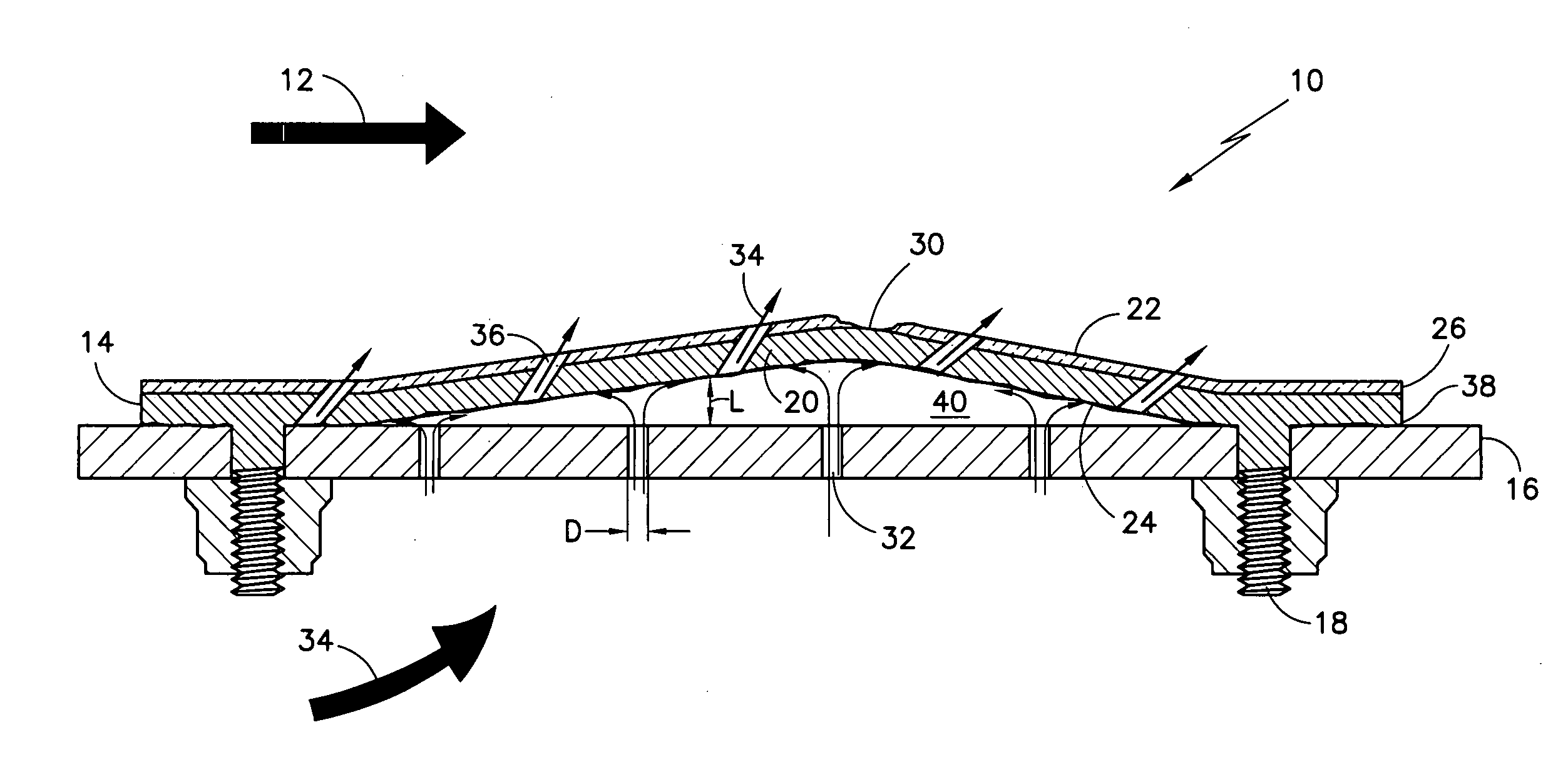
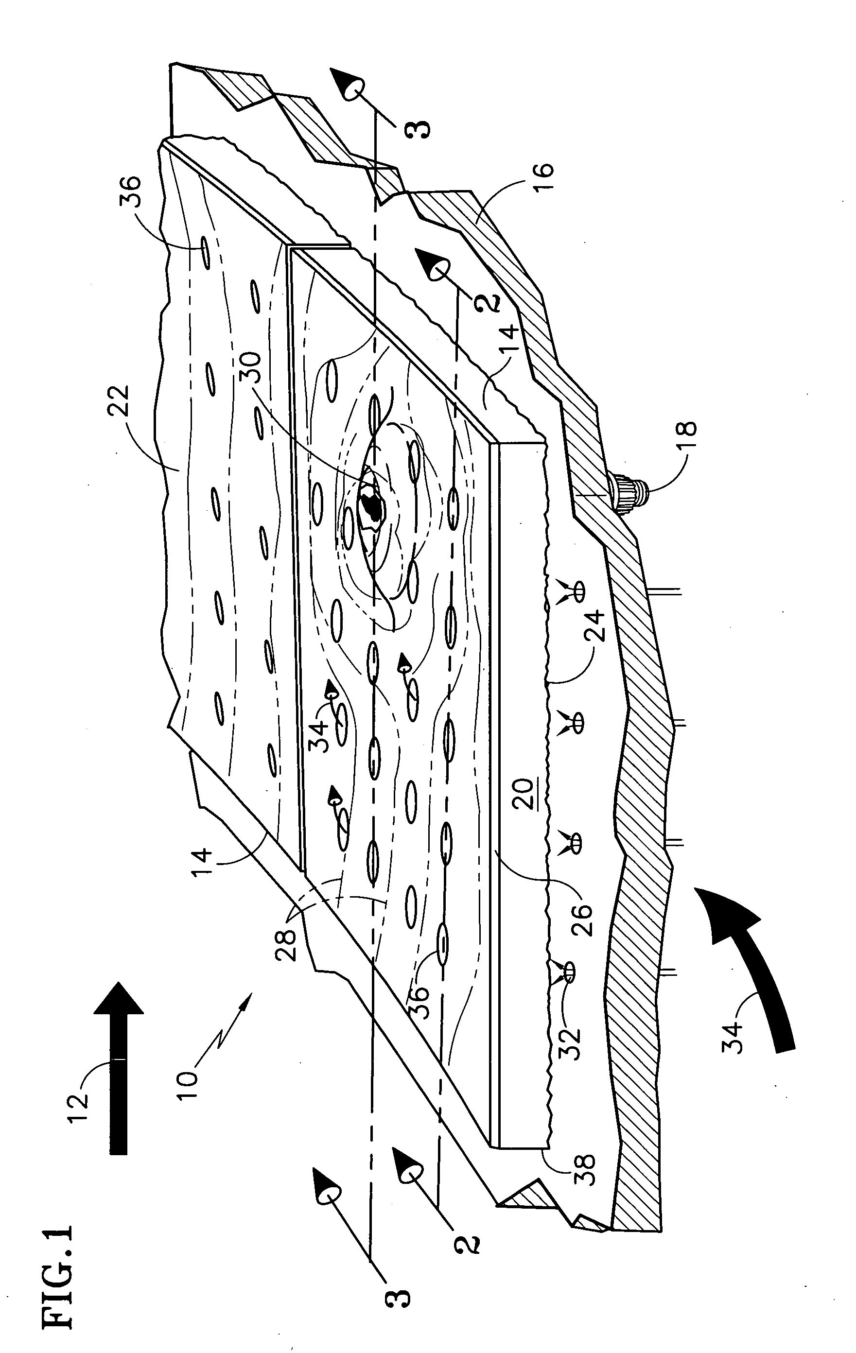
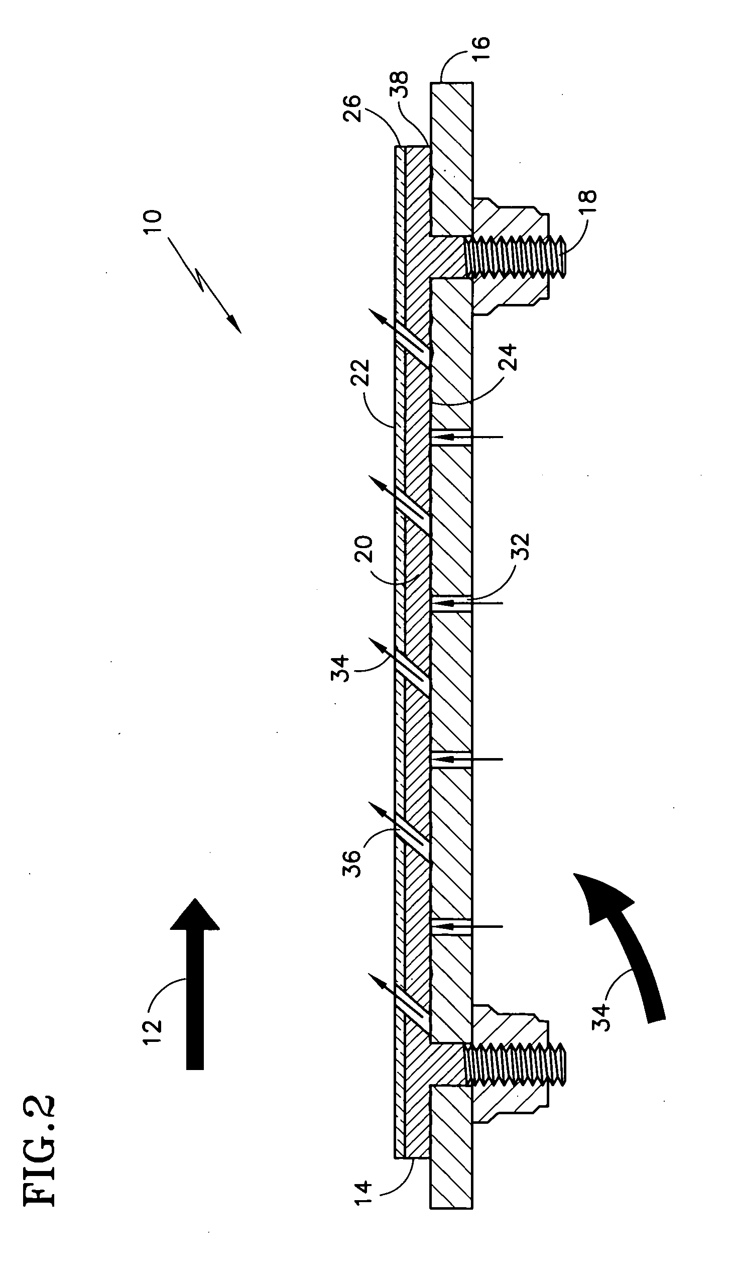
[0016]Referring first to FIG. 1, an exemplary structure 10 with adaptive cooling, such as a gas turbine combustor heatshield or augmentor liner for example, is exposed directly to hot gas path air 12. A liner 14 is affixed to a mounting support 16 by fastening means 18 such as threaded studs, bolts, rivets, welds, or other fastening means known in the art. A liner wall 20 has a hot surface 22 facing away from the support 16 and a cold surface 24 contacting the support 16. The liner wall 20 may be made from a high temperature, cast, forged or sheet material such as Nickel or Cobalt for example. The hot surface 22 may also include one or more layers of thermal barrier coating (TBC) 26, such as a metallic or ceramic material, for improved insulation from the gas path air 12. Thermal gradient lines 28 depict the temperature differential across the hot surface 22 and indicate that a localized hot spot 30 location is present in the area of one of the liners 14. Spallation of the TBC layer...


PUM


Abstract

Disclosed are exemplary structures with adaptive cooling and methods of adaptively cooling structures. A liner is affixed to a support and the liner deflects away from the support when exposed to a localized hot spot in a hot fluid stream. The liner deflection creates a chamber between the liner and support, allowing cooling air to impinge against the liner, thus mitigating the effects of the hot spot. By providing impingement cooling only where needed, the amount of air needed for cooling is reduced.

Description

BACKGROUND OF THE INVENTION[0001](1) Field of the Invention[0002]This disclosure generally relates to cooled structures and more specifically to structures with adaptive cooling for use in hot environments such as found in gas turbine engines.[0003](2) Description of the Related Art[0004]Gas turbine engines are used for powering military and commercial aircraft, ships and electrical generators. Turbine engines operate according to a continuous Brayton cycle where a compressor pressurizes incoming air, fuel is added and the mixture is ignited in a combustor to produce a flowing stream of hot gas. The hot gas is referred to as gas path air or primary air. The gas path air is compressed, used for combustion, and then expands through a turbine before exiting the engine as thrust. The turbine extracts energy from the gas path air and, in turn, powers the compressor via a common shaft. Some military applications may introduce fuel in an augmentor downstream of the turbine, where it is als...

Claims


Application Information

Patent Timeline
Patent Type & Authority Applications(United States)
IPC IPC(8): F02C7/18
CPCF23R3/002F23R3/04Y02T50/675Y02T50/67F23R2900/03044Y02T50/60
Inventor DIERBERGER, JAMES A.
Owner RTX CORP
Why Eureka
Try Eureka