Inertia sensor

a sensor and inertia technology, applied in the field of inertia sensors, can solve the problems of low manufacturing cost and difficult sensor processing of signals, and achieve the effect of reducing the size of the sensor and facilitating the process

Inactive Publication Date: 2010-04-01
KK TOSHIBA
View PDF3 Cites 63 Cited by
  • Summary
  • Abstract
  • Description
  • Claims
  • Application Information

AI Technical Summary

Benefits of technology

[0009]According to the present invention, there is provided a multi-axis accelerometer or a multi-axis angular rate sensor which can be made by an easy process and the size of which can be greatly reduced.

Problems solved by technology

In general, the sensor described above making use of the change of the capacitance has a disadvantage in that it is difficult for the sensor to process a signal because a formed capacitance is very small although the sensor has an advantage in that a manufacturing cost is low.

Method used


Image

  • Inertia sensor
  • Inertia sensor
  • Inertia sensor

Examples


embodiment 1

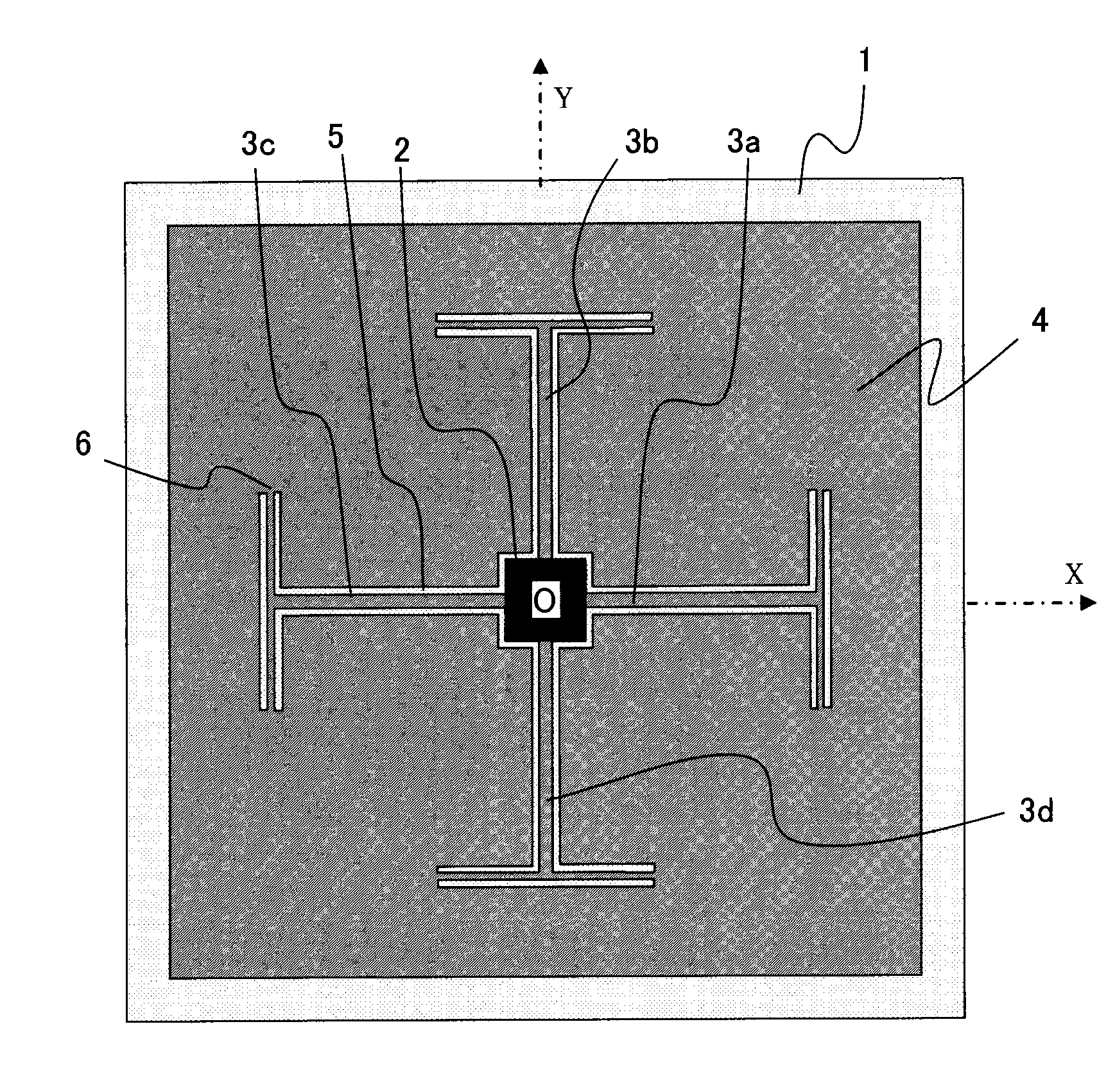
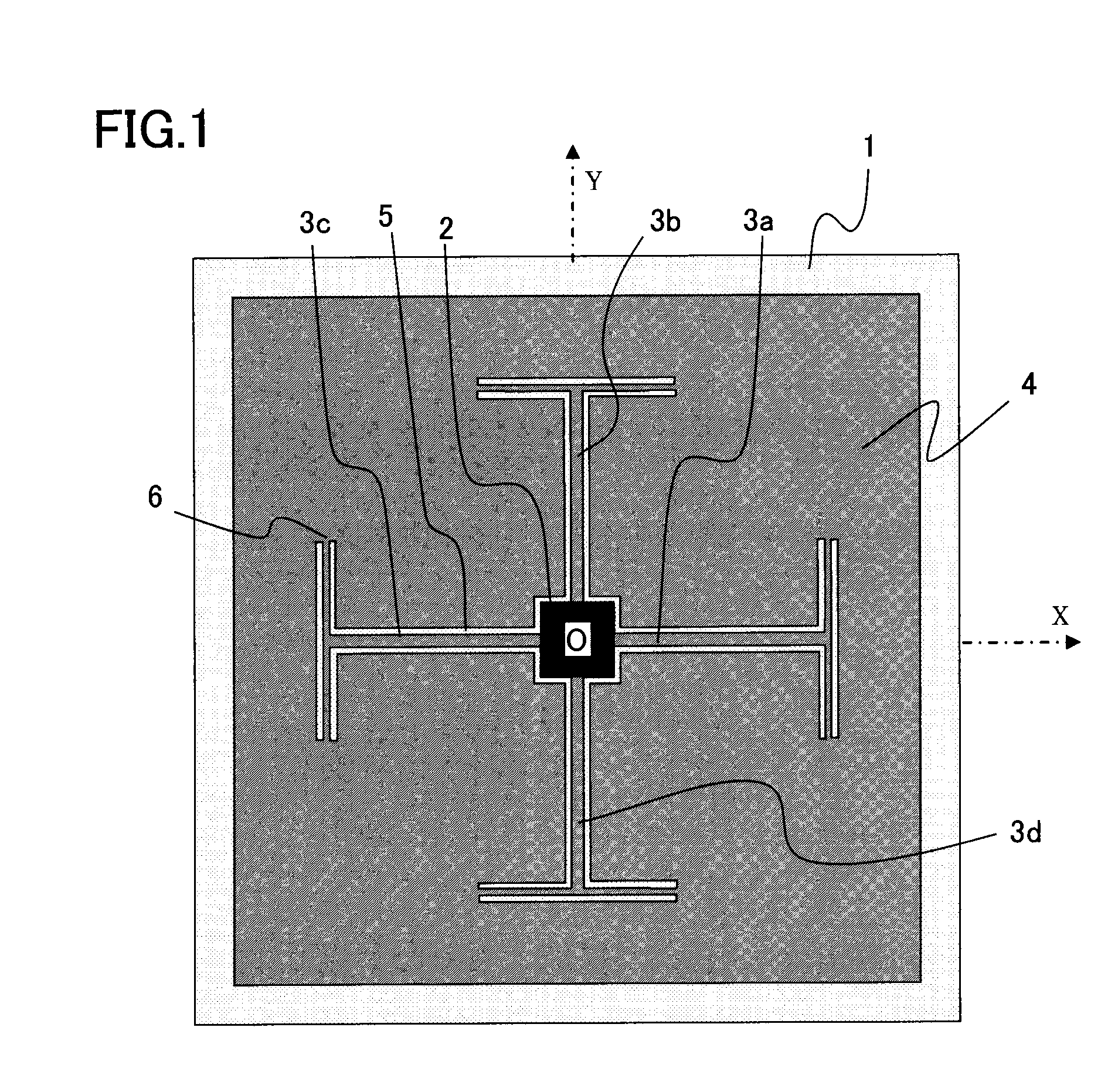
[0040]An inertia sensor of an embodiment 1 has a substrate, a flat proofmass formed on the substrate and having a stacked structure including at least a lower electrode, a piezoelectric film, and an upper electrode, an anchor unit formed in a cutout inside of the proof mass and fixed on the substrate, and a plurality of flat piezoelectric beams each having one end connected to the proofmass, the other end connected to the anchor unit, and having a stacked structure formed in a cutout portion in the proofmass and including at least a lower electrode, a piezoelectric film, and an upper electrode. The inertia sensor enables to detect an acceleration applied on the proofmass based on the charges generated to the respective electrodes of the detection beams.

[0041]The inertia sensor of the embodiment is an accelerometer having the above arrangement. The accelerometer can cancel the influence of warp and residual stress generated to the proofmass and the piezoelectric films constituting th...

first modification of embodiment 1

[0081]The first modification is an example in which piezoelectric beams 3a to 3d have electrodes arranged differently from those of the embodiment 1. FIGS. 14 and 15 are explanatory views of a detection principle when accelerations are applied to an accelerometer of the first modification in X- and Z-axis directions.

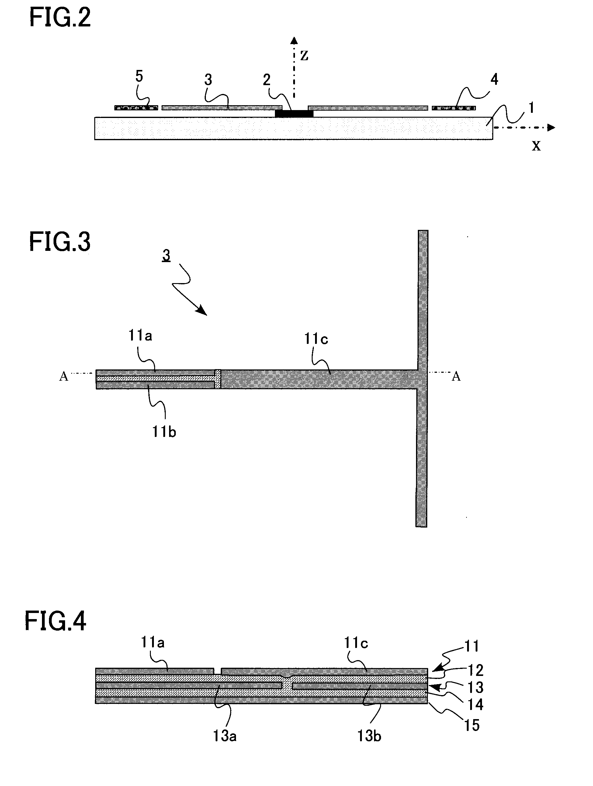
[0082]An upper electrode 11 is divided to upper sub-electrodes 11a, 11b and 11c in a width direction, a lower electrode 15 is also divided to lower sub-electrodes 15a, 15b, and 15c in the width direction. A first differential amplifier 16a is connected between the upper electrodes 11a, 11b and between the lower electrodes 15a, 15b, and a second differential amplifier 17a is connected to an intermediate electrode 13a and between an upper and lower electrodes 11c, 15c.

[0083]A case that an acceleration is applied to the piezoelectric beam 3a in a Y-axis direction will be examined. As shown in FIG. 14, since the piezoelectric beam 3a is flexed by force Fy in the Y-axis dire...

second modification of embodiment 1

[0091]An accelerometer of a second modification is the same as that of the embodiment 1 except that the piezoelectric beams of the accelerometer of the embodiment 1 have a unimorph structure although the accelerometer of the embodiment 1 has the bimorph structure. Accordingly, the description of overlapping contents is omitted.

[0092]FIG. 16 is a cross sectional view of a piezoelectric beam of the second modification. FIG. 16 corresponds to FIG. 4 of the embodiment 1. The piezoelectric beam has a stacked structure composed of an upper electrode 11, a piezoelectric film 19, and a lower electrode 15 stacked from an upper surface thereof in this order.

[0093]The same effect as that of the embodiment 1 can be also obtained even in the second modification in which the piezoelectric beams have the unimorph structure.


PUM


Abstract

A multi-axis accelerometer or a multi-axis angular rate sensor which can be made by an easy process and the size of which can be greatly reduced is provided. An inertia sensor has a substrate, a flat proofmass formed on the substrate and a stacked structure including at least a lower electrode, a piezoelectric film, and an upper electrode, an anchor unit formed in a cutout inside of the proofmass and fixed on the substrate, and a plurality of flat piezoelectric beams each having one end connected to the proofmass, the other end connected to the anchor unit, and a stacked structure formed in a cutout inside of the proofmass and including at least a lower electrode, a piezoelectric film, and an upper electrode, wherein the inertia sensor enables to detect an acceleration applied on the proofmass based on charges generated to the electrodes of the piezoelectric beams.

Description

CROSS-REFERENCE TO RELATED APPLICATION[0001]This application is based upon and claims the benefit of priority from Japanese Patent Applications No. 2008-248308, filed on Sep. 26, 2008, the entire contents of which are incorporated herein by reference.FIELD OF THE INVENTION[0002]The present invention relates to an inertia sensor using a piezoelectric device capable of detecting an acceleration or an angular velocity in two- or three-axis directions.BACKGROUND OF THE INVENTION[0003]A multi-axis accelerometer and a multi-axis angular rate sensor which are small in size and has high reliability are desired by electronics industries, automobile industries, machine industries, and the like.[0004]To cope with the demand, a capacitive type accelerometer is widely used as a multi-axis accelerometer. The capacitive type accelerometer is arranged such that a proofmass is connected to anchor units disposed at several positions on a substrate through springs, and the offset of the proofmass gene...

Claims


Application Information

Patent Timeline
Patent Type & Authority Applications(United States)
IPC IPC(8): G01C19/56G01C19/5656G01C19/5663G01P15/09G01P15/18H01L41/08H01L41/18H01L41/187H01L41/22H01L41/316
CPCG01P15/0802G01C19/5719G01P15/18G01P15/0922G01P2015/082
Inventor KAWAKUBO, TAKASHINAGANO, TOSHIHIKONISHIGAKI, MICHIHIKO
Owner KK TOSHIBA
Why Eureka
Try Eureka