
Maple syrup production spout assembly with backflow check valve

a backflow check valve and maple syrup technology, applied in the field of maple syrup production, can solve the problems that the current maple syrup spouts do not prevent sap from flowing back into, and achieve the effects of reducing or preventing the backflow of sap, reducing microbial contamination of the taphole, and increasing soil-based water uptake by the tr

Active Publication Date: 2010-04-01
UNIVERSITY OF VERMONT
View PDF26 Cites 8 Cited by
  • Summary
  • Abstract
  • Description
  • Claims
  • Application Information

AI Technical Summary

Benefits of technology

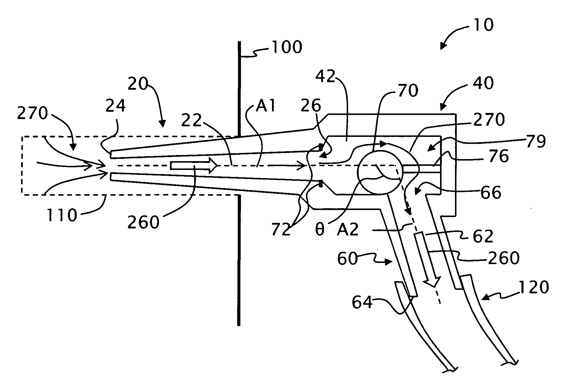
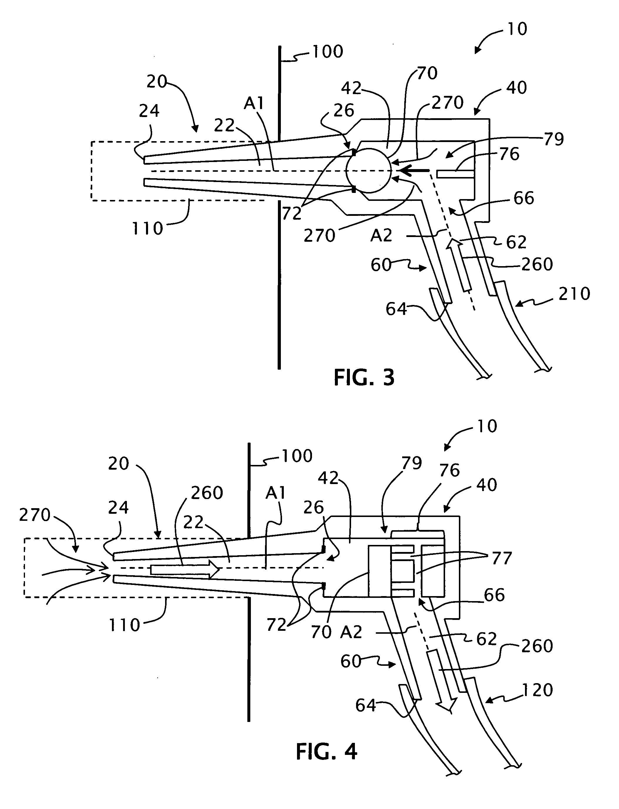
[0008]Current maple syrup spouts do not prevent sap from flowing back into the taphole when used in vacuum-based maple syrup production systems. The spout assembly of the present invention greatly reduces or prevents the backflow of sap into the tree through the use of a backflow check valve. This reduces microbial contamination of the taphole, increases soil-based water uptake by the tree, and increases sap yield for maple syrup production. The spout assembly can be manufactured separately, incorporated (retrofitted) into existing spout assembly designs, or incorporated into a spout assembly adapter that attaches to existing spout assemblies. Maple producers that utilize vacuum-based systems in their operations could benefit from the use of the maple spout assembly of the present invention.
[0011]A third aspect of the invention is a method of extracting sap from a maple tree. The method includes providing a spout assembly having an input end and output end, a main body section having an interior chamber fluidly connected to the input and output ends via respective input and output channels and that contains a backflow check valve that only allows sap to flow through the chamber from the input end to the output end. The method also includes forming a taphole in the maple tree and inserting the spout assembly input end into the taphole. The method further includes applying a vacuum to the spout assembly output end, wherein the application of the vacuum is subject to interruption, and substantially preventing sap that has exited the tree from reentering the tree through the spout assembly via activation of the backflow check valve during the interruption.

Problems solved by technology

Current maple syrup spouts do not prevent sap from flowing back into the taphole when used in vacuum-based maple syrup production systems.

Method used


Image

  • Maple syrup production spout assembly with backflow check valve
  • Maple syrup production spout assembly with backflow check valve
  • Maple syrup production spout assembly with backflow check valve

Examples


Embodiment Construction

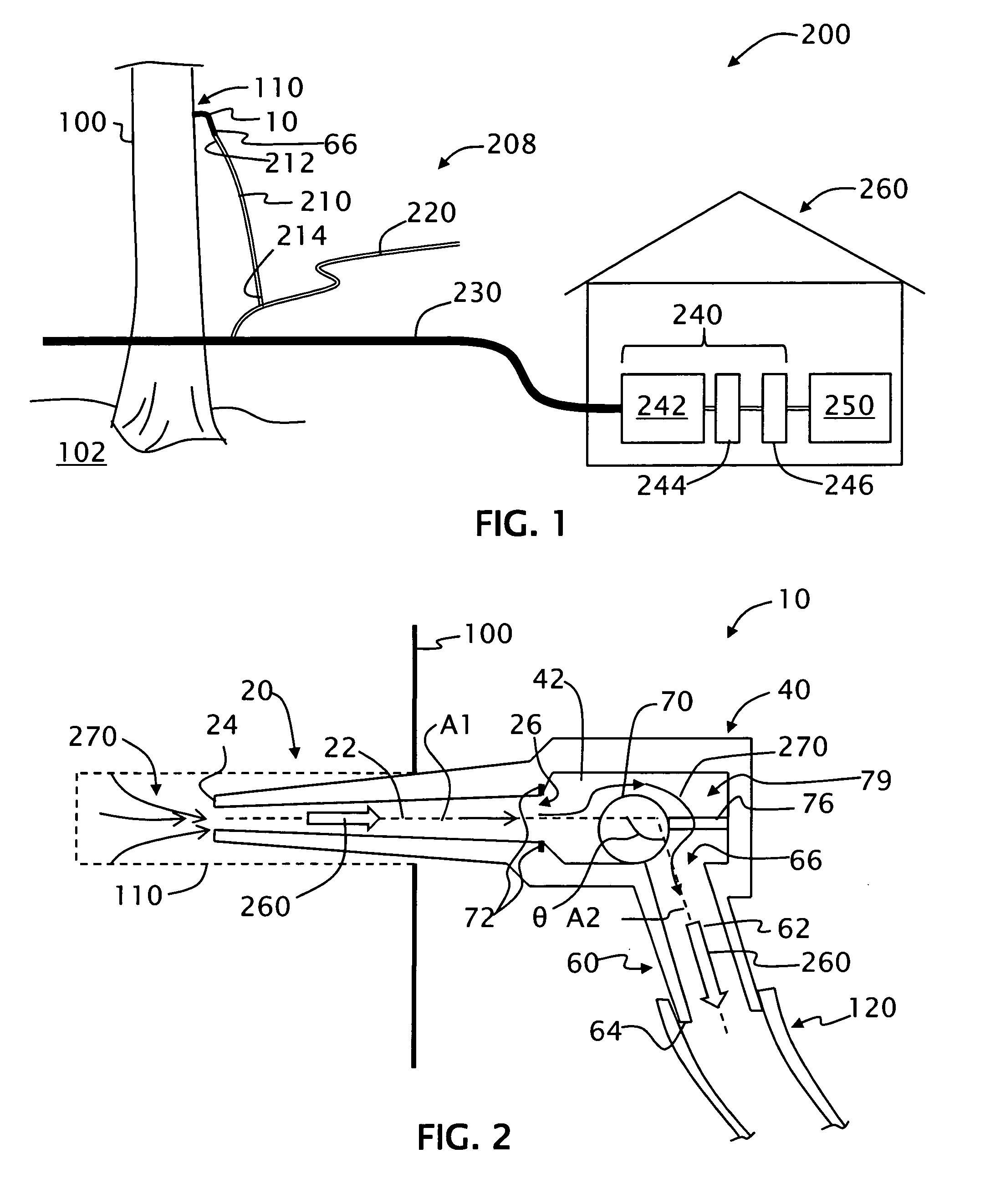
[0024]FIG. 1 shows a schematic diagram of an example maple syrup production system 200 that includes spout assembly 10 connected to tree 100 at a taphole 110 formed therein. Spout assembly 10 is described in greater detail below. System 200 includes a line system 208 that includes a dropline 210, a lateral line 220 and a mainline 230. A first end 212 of a dropline 210 is fluidly connected to an output end 66 of spout assembly 10 while the other end 214 is fluidly connected to lateral line 220.

[0025]Lateral line 220 in turn is operably connected to mainline 230, which in turn is operably connected to vacuum pump system 240 that includes a vacuum pump 242, an extractor 244 and a sap storage tank 246 An evaporator 250 is operably connected to vacuum pump system 240 Vacuum pump system 240, extractor 244, storage tank 246 and evaporator 250 are shown as housed in a sugarhouse 260. System 200 thereby provides vacuum-assisted fluid communication between taphole 110 and evaporator 250 so th...


PUM


Abstract

A maple syrup production spout assembly (10) with a backflow check valve (79) is disclosed. The spout assembly is designed for use with vacuum-based maple syrup productions systems (200) and is used to prevent the backflow of sap (270) into the maple tree (100) and thus prevent the drying out of the taphole (110) due to microbial contamination. Certain existing maple production spout assemblies can be retrofitted to form the backflow check valve spout assembly disclosed herein. Methods of using the spout assembly in maple syrup production are also disclosed.

Description

FIELD OF THE INVENTION[0001]The present invention relates generally to maple syrup production, and in particular relates to spout assemblies used in vacuum-based maple syrup production systems.BACKGROUND ART[0002]Maple syrup production involves drilling holes into (i.e., “tapping”) maple trees, collecting the sap that exudes from the wound, and then reducing or “sugaring” down the sap using reverse osmosis and evaporators to form the final syrup. Details of maple syrup production are described in the publication entitled “North American Maple Syrup Producers Manual” (second edition), produced by Ohio State University, in cooperation with the North American Maple Syrup Council, and edited by Heiligmann, Koelling and Perkins, which is incorporated by reference herein by way of background information.[0003]The traditional way of collecting maple sap uses buckets at the tap source. The sap is then collected in a tank and then transported to the “sugarhouse” for processing. Over the year...

Claims


Application Information

Patent Timeline
IPC IPC(8): A01G23/14A01G23/10F16K15/00
CPCA01G23/14F16K15/04F16K15/021Y10T137/7837Y10T137/7866Y10T137/86083
Inventor PERKINS, TIMOTHY D.
Owner UNIVERSITY OF VERMONT
Learn More