Mist generator for sterilizing forced air systems

a forced air system and generator technology, applied in the direction of gaseous substances, other medical devices, disassembly and maintenance, etc., can solve the problems of puddles of leaked water around the patient and on the operating room floor, heavy water filled blankets, and high patient discomfort, so as to improve sterility

Pending Publication Date: 2020-11-05
LEWIS RANDALL J
View PDF0 Cites 8 Cited by
  • Summary
  • Abstract
  • Description
  • Claims
  • Application Information

AI Technical Summary

Benefits of technology

[0027]In one embodiment, a mist generator for improved sterility of blowers comprises a chamber having a top wall with an opening therein, sidewalls, and a bottom wall. An inlet duct or aperture is adapted for attachment to a first hose which, in turn, is adapted for attachment to an output opening of the blower for delivery of forced air into the chamber to carry disinfectant misted air. An output duct, comprising the opening in the top wall, is adapted for attachment to a second hose which, in turn, is adapted for attachment to a blower inlet opening of the blower for delivery of disinfectant misted air through internal components of the blower. The mist generator improves sterility of the blower to mitigate microbial contamination of forced air delivery systems.
[0028]In operation, the mist generator chamber is first partially filled with a liquid disinfectant, which is taken up by the forced air circulating through the chamber and delivered into the internal components of the blower to clean and sterilize the components. Once the chamber is dry, water is placed in the chamber and is taken up by the circulating air, which becomes saturated with water vapor. The residual disinfectant in the system is dissolved into the water vapor circulating in the saturated air. A desiccant or other dry material is then placed in the chamber. The water vapor and dissolved residual disinfectant are taken up in the dry material. When the cycle is complete, the chamber is disconnected and discarded, the airlines reconnected, if required, and air can then be circulated through an internally sterile system. After use of the antimicrobial chamber, this sanitation of the internal components prevents unsterile air currents containing microbes from being delivered from the blower when it is in-line with a patient warmer, lifter or other machine, thereby decreasing the risk of infection from blower contaminants.
[0029]In another embodiment, there is provided a mist generator for communication with an air stream of a blower that provides controlled forced air delivery. The mist generator comprises a disinfectant filter formed as a sterilizing grid having a screen coated with a soft porous surface material impregnated with a liquid disinfectant. The soft porous surface material is operative to release the liquid disinfectant, thereby improving sterility of the blower and mitigating microbial contamination of forced air delivery systems.
[0030]The mist generator delivers vaporized disinfectant through a blower and / or blower system in order to sterilize the blower and / or blower system and decrease the possibility of exposure to infecting microbes. It is intended to perform internal sterilization of the blower and / or blower system, including the blower, blower vents, internal blower components, air vents, and hoses. Advantageously, the mist generator significantly improves the sterility of forced air systems employing forced air, heated air and / or cooled air, including, for non-limiting example, hospital machines / health care equipment, and portable oxygen machines. In some embodiments the antimicrobial mist generator is employed in commercial and / or residential forced air systems for facilitating and / or maintaining internal sterility and decontaminating the ambient air. Hospital machines / health care equipment contemplated include respirators, anesthesia machines, and the like. Commercial and / or residential forced air systems include a full range of blower / forced air devices for use with heaters, coolers, and air blowers, such as those used in commercial and / or residential forced air systems, as well as forced air systems such as air conditioners and the like, used in land vehicles, including trucks, automobiles, trailers and tractors. These systems may include heating or cooling systems for residential and commercial buildings (hospitals, high-rise, or otherwise that involve units sharing forced air system components or vents), transportation vehicles (cruise ships, boats, trains, airplanes, and the like). Savings in reduced material, low production and installation costs, as well as ease of use and improved sterility, represent advancements afforded by the mist generator during operation of these blower systems.
[0031]In yet another embodiment, the mist generator for improved sterility of blowers having controlled forced air comprises a chamber having a top wall with an opening therein, sidewalls and a bottom wall. The opening in the top wall traverses into the chamber, which is adapted to receive a disinfectant. The mist generator has an inlet duct adapted for attachment to a first hose which, in turn, is adapted for attachment to an output opening of the blower for delivery of forced air into the chamber. In one aspect, the opening in the top wall may serve as the output opening for the mist generator, and a separate output opening may not be necessary. In another aspect, an output duct is provided in addition to the top wall opening. The output duct is adapted for attachment to a second hose which, in turn, is adapted for attachment to a blower inlet opening of the blower for delivery of disinfectant misted air, water, and clean air through internal components of the blower. The mist generator improves the sterility of the blower to mitigate microbial contamination of forced air delivery systems.
[0032]In yet another embodiment, the mist generator for improved sterility of blowers having controlled forced air delivery, comprises a disinfectant filter formed as a sterilizing grid having a screen coated with a soft porous surface material impregnated with a liquid disinfectant. With this embodiment, the disinfectant is released from the soft porous surface into the air passing through the filter. When the filter is dry, it can be removed and impregnated with clean or sterile water. The moistened filter is then reinserted, and the air flowing through the system takes up the water. This procedure can be repeated, or another separate filter, moistened with water, may be used. This water is operative to dissolve residual disinfectant within the system. The water, including the contained disinfectant, is removed by inserting a dry filter and allowing the circulating water to be taken up by the dry filter, which is removed and discarded. Water may also be removed by a dehumidifier, if installed. Cyclical operation of mist generator in this manner improves the sterility of the blower to mitigate microbial contamination of forced air delivery systems.

Problems solved by technology

If a fluid-filled device leaks or ruptures, the heated water disadvantageously creates puddles of leaked water around the patient and on the operating room floor.
Water filled blankets are heavy, and the patient may find these blankets highly uncomfortable.
In addition, bacteria often contaminate the water contained in the warm water devices, potentially increasing infection risk.
Release of the warm air can cause currents of unsterile air, containing bacteria, to surround the patient or the operative site, increasing prospects for infections.
Heating of the blanket is not achieved by the passage of warm air.
The device disclosed by the Feher patent does not use circulation of warm air in a closed system to warm the bed of a patient, and there is no sterilization of the internal portion of the system, increasing the possibility of infecting the patient and workers in the operating room.
The device does not provide patient warming.
Although there are filters in the device, there is no sterilization of the interior of the blower, as recommended by the FDA.
Standards being implemented require frequent cleaning and sterility owing to findings that contaminated forced air can increase the concentration of contaminated airborne particles over a surgical site.
Despite the finding that forced-air blowers need regular maintenance and cleaning, the current cleaning method typically involves simply wiping down the blower device.
Wipe-down of the blower fails to clean the inside of the blower itself, and therefore forced-air from the blower typically poses contamination threats to the surgical site when the forced-air blower is being used with patient warmers or lifters.

Method used


Image

  • Mist generator for sterilizing forced air systems
  • Mist generator for sterilizing forced air systems
  • Mist generator for sterilizing forced air systems

Examples


Embodiment Construction

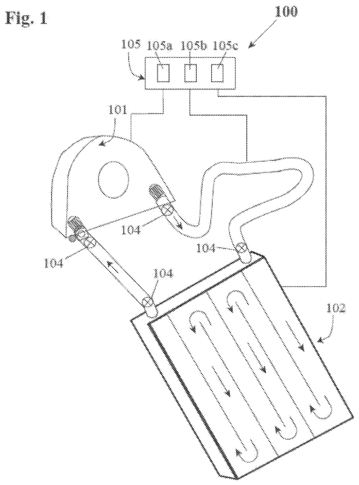
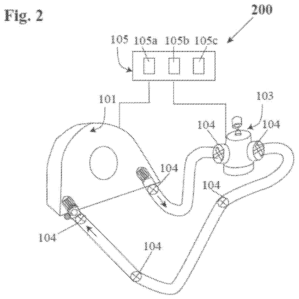
[0054]The objective of the invention is to provide a mist generator for delivering an antimicrobial or disinfectant mist to a blower and / or blower system in order to sterilize the blower and / or blower system and decrease the possibility of exposure to infecting microbes. The mist generator is simple, inexpensive, easy to use and install, and essentially disposable. The subject mist generator is intended to perform internal sterilization of the blower and / or blower system, including the blower, blower vents, internal blower components, air vents, and hoses. The present invention relates to improvements in the sterility of forced air systems employing forced air, heated air and / or cooled air, including, for non-limiting example, hospital machines / health care equipment, portable oxygen generators / commercial and / or residential forced air systems for facilitating and / or maintaining internal sterility. Hospital machines / health care equipment contemplated include respirators, anesthesia ma...


PUM

PropertyMeasurementUnit
pHaaaaaaaaaa
pore sizeaaaaaaaaaa
diameteraaaaaaaaaa

Abstract

A mist generator is a standalone device that improves the internal sterility of controlled forced air systems. Sterilizing mist is generated when forced air circulates above or through a liquid disinfectant. The disinfectant is taken up into the circulating air and distributed throughout the internal structure of the system, sterilizing its internal surfaces. The mist generator contains no ionizers, atomizers, ultraviolet lamps, or other electric or mechanical devices.In one embodiment, the mist generator has a chamber with an inlet adapted for attachment to a blower or duct delivering forced air into the chamber. The chamber also includes an output duct or aperture adapted for attachment to a second hose which, in turn, is adapted for attachment to the inlet of the blower for delivery of disinfectant-misted air through internal components of the blower. Alternatively, there is used a disinfectant filter formed as a sterilizing grid having a screen coated with a soft porous surface material impregnated with a liquid disinfectant. The soft porous surface material releases said liquid disinfectant when forced air moves through the filter and through the system. In both embodiments, sterile water can be introduced to take up residual disinfectant and the vapor is captured in a dry filter or desiccant material and removed from the system.In the alternative embodiment, the sterilizing mist produced by the uptake of liquid disinfectant into circulating air and distributed throughout the forced air system can be formed when air from a blower or air handler is circulated across a sterilizing screen with a porous surface material impregnated with a liquid disinfectant. The antimicrobial mist is distributed throughout the system and acts to disinfect the internal surfaces and components. Additional water may be added to the sterilizing screen and distributed similarly by the forced air. A dry, desiccating filter, remote from the blower, traps the water and any residual disinfectant as it exits from the system. A dehumidifier, if installed, may also be used to remove water and can be readily emptied.The mist generator improves the sterility of the blower and mitigates microbial contamination of forced-air delivery systems.

Description

CROSS-REFERENCE TO RELATED APPLICATIONS[0001]This application is a continuation-in-part of applicant's co-pending U.S. patent application Ser. No. 16 / 841,387, filed Apr. 6, 2020 which, in turn, is a continuation-in-part of application Ser. No. 15 / 722,822, filed Oct. 2, 2017 which, in turn, is a continuation-in-part of applicant's co-pending U.S. patent application Ser. No. 15 / 334,507, filed Oct. 26, 2016, now U.S. Pat. No. 9,901,483 which, in turn, is a continuation-in-part of U.S. patent application Ser. No. 15 / 056,120, filed Feb. 29, 2016, now U.S. Pat. No. 9,504,601, the disclosures of which are hereby incorporated in their entirety by reference thereto.1. FIELD OF THE INVENTION[0002]The present invention relates to improvements in sterility of forced air systems; and, more particularly, to an antimicrobial mist generator utilized with systems employing forced air, heated air or cooled air, such as hospital equipment, health care equipment, commercial and / or residential forced ai...

Claims


Application Information

Patent Timeline
Patent Type & Authority Applications(United States)
IPC IPC(8): A61L9/14A61L9/03
CPCA61L2209/14A61L9/14A61L9/032A61L9/122A61L9/127A61L2209/11A61L2209/132A61L2209/16A61M16/00A61M2202/203A61M2202/206A62B7/10
Inventor LEWIS, RANDALL J.
Owner LEWIS RANDALL J
Why Eureka
Try Eureka