Light source

a technology of light source and controller, applied in the field of light source, can solve the problem of relatively high power consumption of the controller, and achieve the effect of reducing power consumption

Active Publication Date: 2010-04-01
SIGNIFY HLDG BV
View PDF12 Cites 54 Cited by
  • Summary
  • Abstract
  • Description
  • Claims
  • Application Information

AI Technical Summary

Benefits of technology

[0004]It is an object of the present invention to provide a lig...

Problems solved by technology

The power consumption of the controller is relatively high, since ...

Method used


Image

  • Light source
  • Light source
  • Light source

Examples


Embodiment Construction

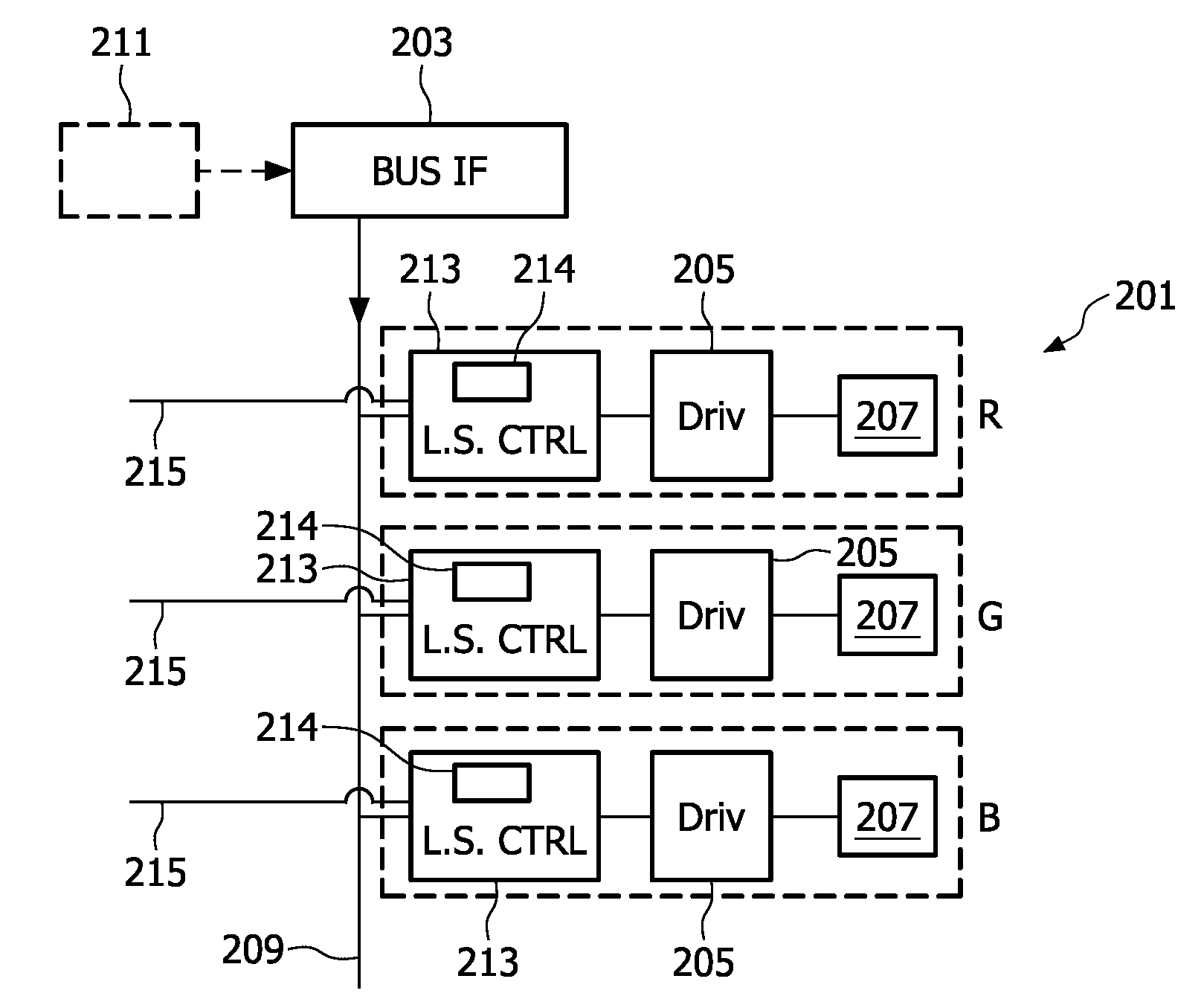
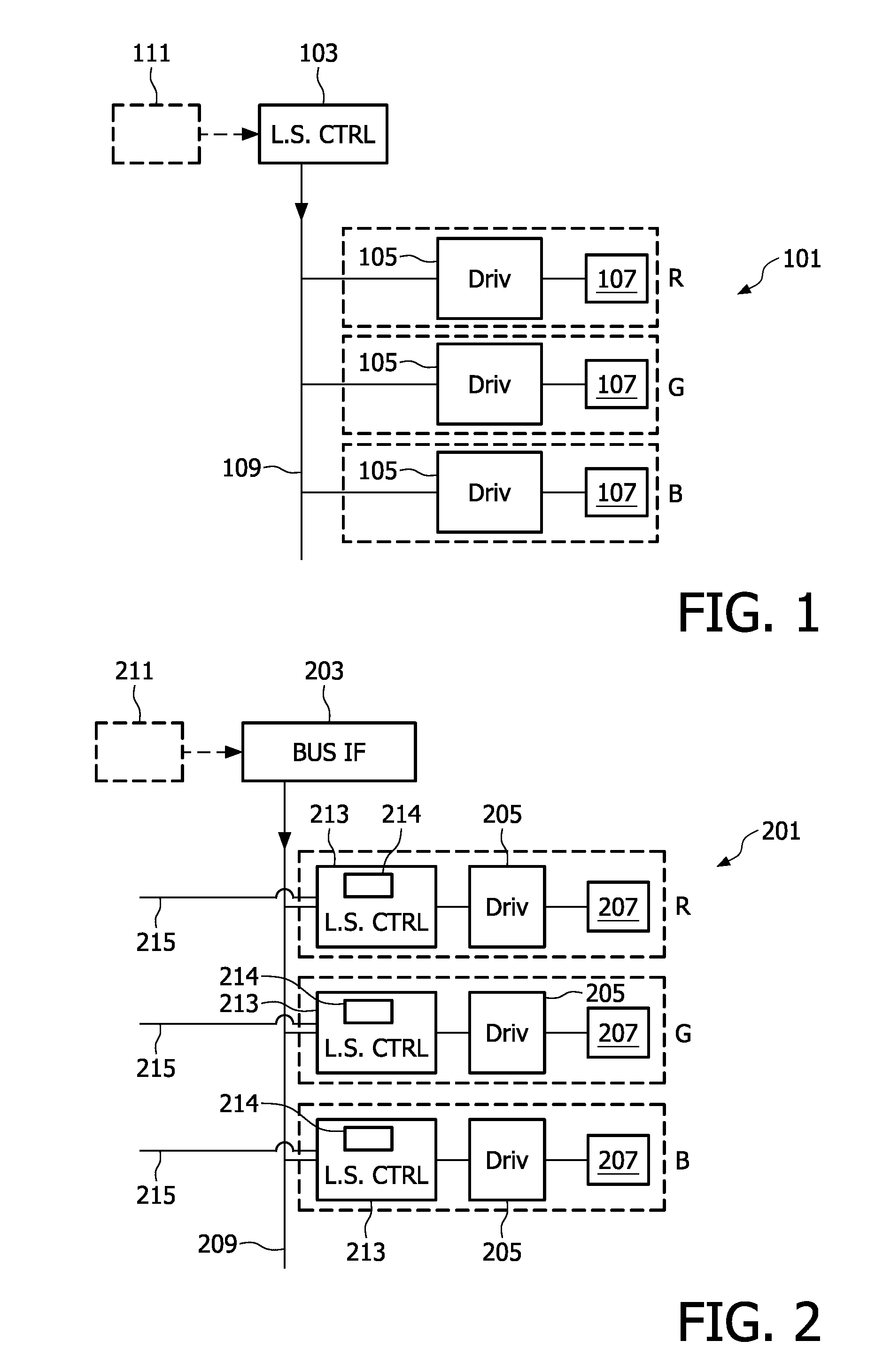
[0037]Referring to FIG. 2 an embodiment of a light source 201 comprises a bus interface (BUS IF) 203, which is connected via a light source bus 209 to several light element controllers 213. The controllers are used for causing the light source 201 to emit light of a desired character, for example as regards color and intensity. The light source bus is set in a broadcasting mode, which means that an output from the bus interface 203 is sent to all light element controllers 213 at the same time.

[0038]Each light element controller 213 is connected to a driver 205 of a light element 207. In the illustrated embodiment there are several light elements 207 of each one of three different colors, namely red (R), green (G) and blue (B), and one light element 207 of each color is shown in FIG. 2. For example, the light elements 207 are LEDs, but any solid state light (SSL) element is incorporated within the scope of this invention. Additionally, the invention is applicable to conventional ligh...


PUM


Abstract

This invention relates to a light source (201) having a plurality of light elements (207) and a control system for controlling the, light elements. The control system comprises a plurality of light element controllers (213), each connected to a respective light element (207), and arranged to obtain light element data; and a bus interface (203), which is connected to the light element controllers (213) via a light source bus (209). The bus interface (203) provides the light element controllers (213) with a general command, and the light element controllers (213) generate light element drive signals on basis of the general command and the light element data.

Description

FIELD OF THE INVENTION[0001]The present invention relates to a light source, which has a plurality of light elements and a control system for controlling said plurality of light elements.BACKGROUND OF THE INVENTION[0002]A conventional light source is schematically shown in FIG. 1. It has a plurality of light elements, such as RGB elements, 107; that is, an element that generates red light, an element that generates green light, and an element that generates blue light. When combined the light elements 107 are able to provide any desired color of the emitted light. In order to obtain a desired color, or character, typically defined as color point, of the emitted light a control system is included in the light source 101.[0003]A main part of the control system is a light source controller 103, which calculates individual drive signals for all of the light elements 107 and feeds the individual drive signals to the individual light elements 107, and more particularly to drivers 105 ther...

Claims


Application Information

Patent Timeline
IPC IPC(8): H05B37/00
CPCH05B37/0254H05B47/18
Inventor DEIXLER, PETERJALINK, CORNELIS JOJAKIMSTRAVERS, PAUL
Owner SIGNIFY HLDG BV
Why Eureka
Try Eureka