Laser microscope apparatus

a microscope and laser technology, applied in the field of laser microscope equipment, can solve the problems of inability to compensate, and it is not possible to efficiently generate the multiphoton excitation

a microscope and laser technology, applied in the field of laser microscope equipment, can solve the problems of inability to compensate, and it is not possible to efficiently generate the multiphoton excitation

US20100079857A1Active Publication Date: 2010-04-01EVIDENT CORP

Image

  • Laser microscope apparatus
  • Laser microscope apparatus
  • Laser microscope apparatus

Examples


first embodiment

[0028]A laser microscope apparatus 1 according to a first embodiment of the present invention will be described below with reference to the drawings.

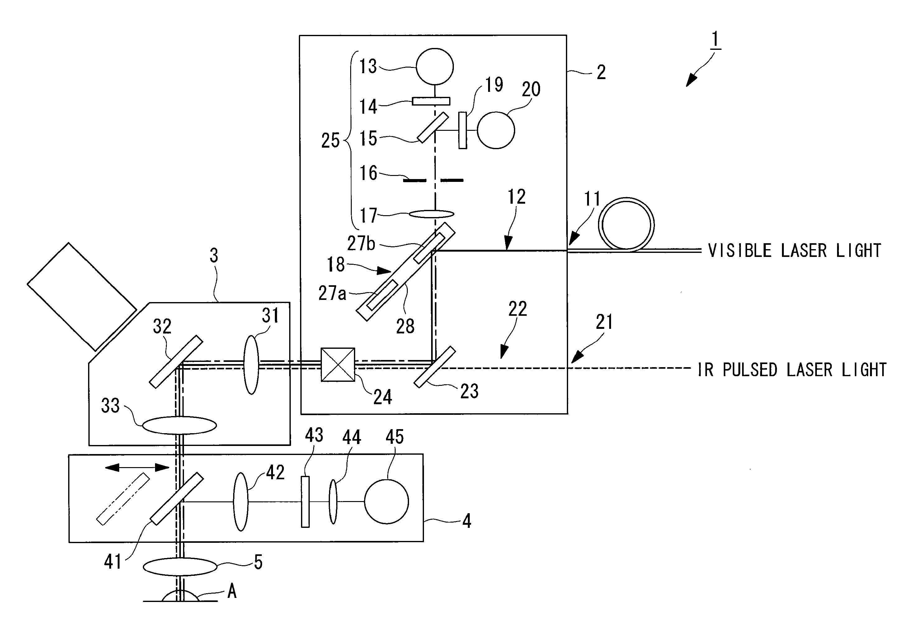
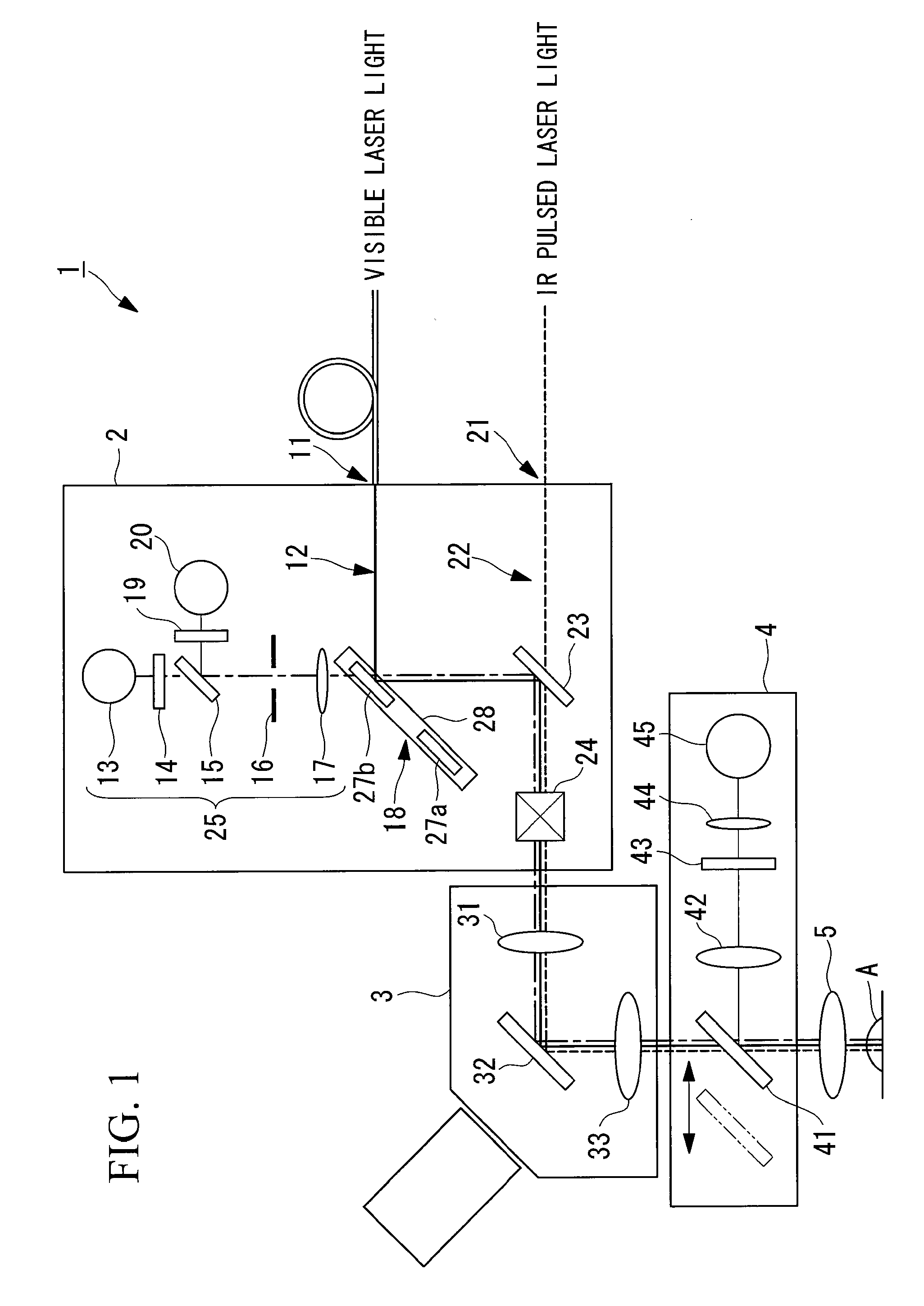
[0029]As shown in FIG. 1, the laser microscope apparatus 1 according to this embodiment includes a scanning unit 2 that scans input laser light, a observation tube 3 that has a plurality of lenses and that guides the laser light from the scanning unit 2, an objective lens (observation optical system) 5 that irradiates a specimen A with the laser light guided by the observation tube 3 and that collects fluorescence produced in the specimen A, and a non-descan detection unit 4 provided between the observation tube 3 and the objective lens 5.

[0030]The scanning unit 2 includes a VIS port 11 to which visible laser light is input, a first light path 12 via which the visible laser light input to the VIS port 11 is guided, an IR port 21 to which IR pulsed laser light (near-infrared ultrashort pulsed laser light) is input, and a second light pat...

second embodiment

[0059]Next, a laser microscope apparatus 51 according to a second embodiment of the present invention will be described with reference to the drawings.

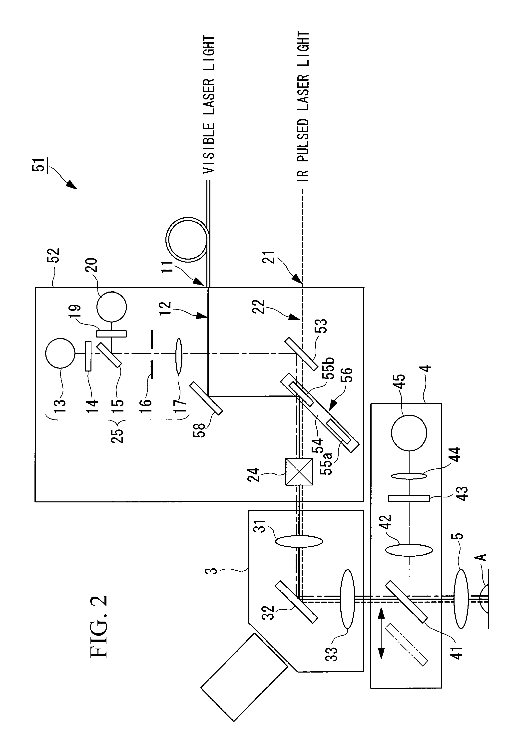
[0060]The difference between the laser microscope apparatus 51 according to this embodiment and that according to the first embodiment is that fluorescence from the specimen A is transmitted at a dichroic mirror combining the light paths of the visible laser light and the IR pulsed laser light. In the following description of the laser microscope apparatus 51 according to this embodiment, a description of parts that are the same as those in the first embodiment will be omitted, and mainly the differences will be described.

[0061]As shown in FIG. 2, the laser microscope apparatus 51 according to this embodiment includes a scanning unit 52 that scans input laser light, a observation tube 3 that has a plurality of lenses and that guides light from the scanning unit 52, an objective lens (observation optical system) 5 that irradiates a spe...


PUM


Abstract

Observation is performed using bright, clear multiphoton fluorescence images produced by efficiently generating a multiphoton excitation effect, without the need for a complex interference film structure. The invention employs a laser microscope apparatus including a first dichroic mirror that reflects visible laser light guided via a first light path and that transmits IR pulsed laser light guided via a second light path to combine the first light path and the second light path; an XY galvanometer mirror that scans the laser light from the first dichroic mirror on a specimen; an objective lens that irradiates the specimen with the scanned laser light and that collects fluorescence produced in the specimen; a second dichroic mirror that reflects the visible laser light and transmits the fluorescence from the specimen; and a detection unit that detects the fluorescence transmitted through the second dichroic mirror.

Description

BACKGROUND OF THE INVENTION[0001]1. Field of the Invention[0002]The present invention relates to a laser microscope apparatus.[0003]This application is based on Japanese Patent Application No. 2008-256253, the content of which is incorporated herein by reference.[0004]2. Description of Related Art[0005]There is a known laser microscope apparatus in the related art which is provided with two light paths via which laser light in different frequency bands is guided and a dichroic mirror that reflects the laser light in one light path and transmits the laser light in the other light path to combine the two light paths (for example, see Japanese Unexamined Patent Application, Publication No. 2004-86009). In this laser microscope apparatus, a specimen is irradiated with infrared pulsed laser light being used as the laser light guided via the first light path, and fluorescence produced by a multiphoton excitation effect is observed. An excitation dichroic mirror that reflects laser wavelen...

Claims


Application Information

Patent Timeline
01 Apr 2010
Publication
US20100079857A1
IPC
G02B21/06; G02B13/14
CPC
G02B2207/114; G02B21/16
Inventors
SASAKI, HIROSHI; KUBO, HIROKAZU