
Method and Apparatus for Providing Wireless Communications Within a Building

a wireless communication and building technology, applied in the direction of selective content distribution, data switching networks, wireless commuication services, etc., can solve the problems of obstructing and interference with wireless signals, wireless signals to fade, and inability to work well with wireless communication within buildings

Active Publication Date: 2010-04-01
OPTICAL CABLE CORPORATION
View PDF60 Cites 205 Cited by
  • Summary
  • Abstract
  • Description
  • Claims
  • Application Information

AI Technical Summary

Benefits of technology

[0013]According to still yet another feature of the one aspect of the present invention, the DC power injector component of the communication system is configured for receiving, processing, and distributing DC power signals and bridging signals while preventing contamination of the DC power signals and the bridging signals with one another via operation of a filter operatively disposed between a signal input arrangement for receiving the DC power signals and the bridging signals and a signal output arrangement for transmission of the DC power signals and the bridging signals.
[0034]According to yet another additional feature of the another further aspect of the present invention, the TV injector component of the communication system is configured for receiving, processing, and distributing a plurality of TV signals and the bridging signals while preventing contamination of the TV signals and the bridging signals with one another via operation of a filter operatively disposed between a signal input arrangement for receiving the TV signals and the bridging signals and a signal output arrangement for distribution of the TV signals and the bridging signals.

Problems solved by technology

However, wireless communication within a building often does not work well, notwithstanding the existence of numerous towers outside of the building.
One problem encountered by wireless communication systems within a building is the obstruction of and interference with the wireless signal.
Physical structures, such as concrete block walls, metal covered wall insulation, and electromagnetic devices such as cordless phones and microwave ovens, can cause a wireless signal to fade.
However, according to U.S. Pat. No. 7,406,300 to Pan, a limitation on such communications has been the difficulty in obtaining signal within a structure such as a residential home, for example.
Among the factors contributing to this difficulty is the inherently limited radio frequency (RF) coverage in and around building structures on account of the metallic content of a building structure that can provide an RF block or otherwise interfere with adequate signal transmission.
Additionally, the various metal objects and the structure of the internal walls, for example, in many cases prevent adequate interior RF coverage so that individually carried cell phones, personal digital assistants and lap top computers cannot consistently receive or transmit a signal at the full range of desired user locations within the building structure.
However, the metallic content of a building structure may interfere with the directed RF signal.
The resulting coverage within the building is thus unpredictable.
Factors such as a call location inside the building, the building location relative to the serving base station location, building construction, repeater site location, and orientation of the repeater antennas can influence and render unpredictable the RF signal capability within the building.
The set up of a dedicated network of inside antennas involves the installation of cabling and associated hardware and this can amount to an overly expensive approach for improving RF signal coverage within a building.

Method used


Image

  • Method and Apparatus for Providing Wireless Communications Within a Building
  • Method and Apparatus for Providing Wireless Communications Within a Building
  • Method and Apparatus for Providing Wireless Communications Within a Building

Examples


Embodiment Construction

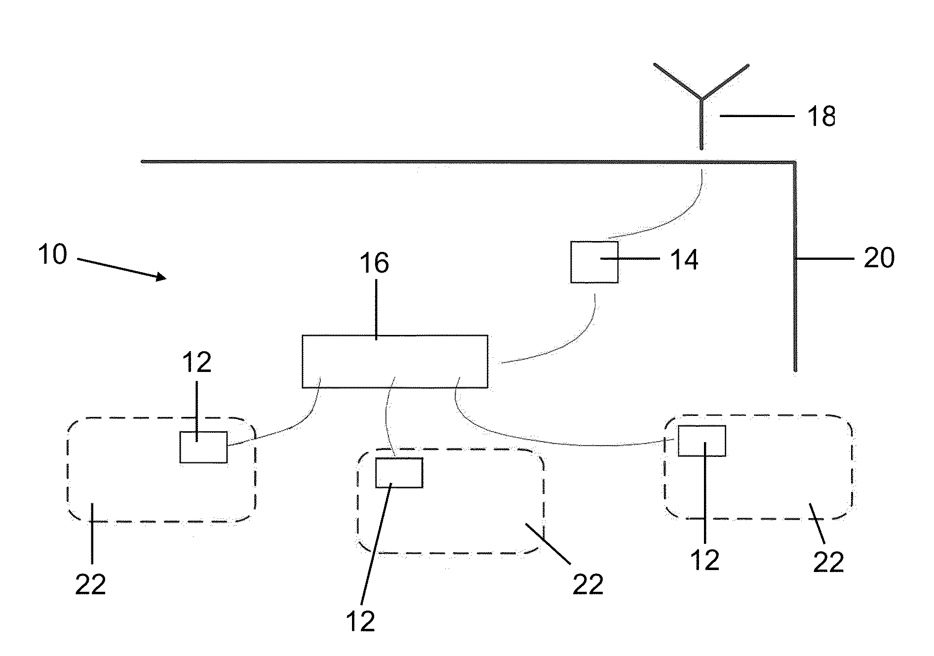
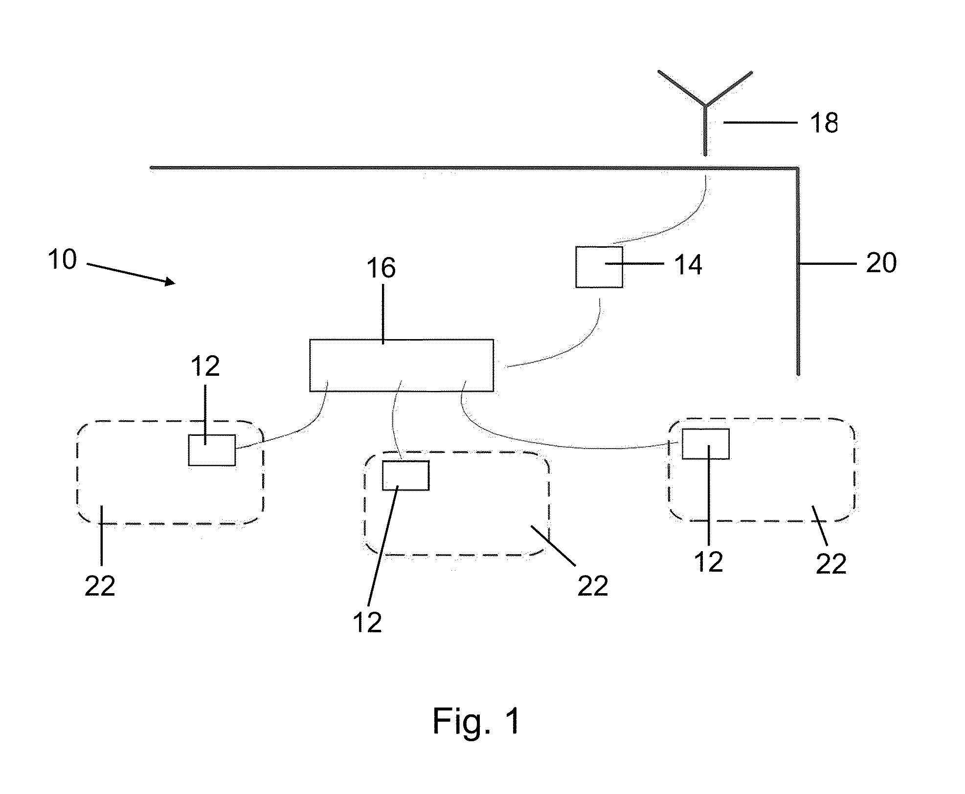
[0049]FIG. 1 shows the overall basic architecture of a wireless distribution secured cabling system 10. The wireless distribution secured cabling system not only supports cellular service provider communications, but also supports other wireless technologies such as local area wireless networks, including networks governed by IEEE 802.11 Wireless LANs. As seen in FIG. 1, the wireless distribution secured cabling system 10 includes faceplates 12, each of which contains an antenna or other radiating element and an active amplifier 14, which serves as a bi-directional repeater for the wireless communication system. The system further includes a patch panel or distribution module 16 which connects multiple cables, which may be either twisted pair or coaxial, to amplifier 14, acting as a power divider and / or an impedance matching device.

[0050]Antenna 18, which may be mounted either outside of a building structure 20 or inside the building structure, is provided. An antenna 18 provides co...


PUM


Abstract

A wireless distribution secured cabling system includes faceplates, each of which contains an antenna or other radiating element and an active amplifier, which serves as a bi-directional repeater for the wireless communication system. The system further includes a patch panel or distribution module which connects multiple cables, which may be either twisted pair or coaxial, to amplifier, acting as a power divider and / or an impedance matching device. An antenna, which may be mounted either outside of a building structure or inside the building structure, provides communications between the structured cabling system and a service provider base station.

Description

RELATED APPLICATION[0001]This is a U.S. non-provisional application relating to and claiming the benefit of U.S. Provisional Patent Application Ser. No. 61 / 194,325, filed Sep. 26, 2008.BACKGROUND OF THE INVENTION[0002]This invention relates to a method and apparatus for providing wireless communications within a building. The demand for wireless communications has grown substantially over the past few years, primarily because it enables users to communicate over a wide range of locations. This demand has been met in part by the placement of numerous cellular towers around the country. However, wireless communication within a building often does not work well, notwithstanding the existence of numerous towers outside of the building. One problem encountered by wireless communication systems within a building is the obstruction of and interference with the wireless signal. Physical structures, such as concrete block walls, metal covered wall insulation, and electromagnetic devices such...

Claims


Application Information

Patent Timeline
Patent Type & Authority Applications(United States)
IPC IPC(8): H04W4/00
CPCH04B7/2606H04W88/04H04N21/654H04L12/189H04W92/18
Inventor REYNOLDS, WILLIAM R.TIMMINS, IAN J.VADEN, STERLINGYANIK, JAMESSEO, SUMIO
Owner OPTICAL CABLE CORPORATION
Learn More