Image formation device and image formation method

a technology of image formation device and image, which is applied in the direction of electrographic process apparatus, instruments, corona discharge, etc., can solve the problems of full-path dielectric breakdown, easy deterioration of the charging function of the charging unit for electrically charging a photosensitive body (e.g. photosensitive drum), and inability to prevent spark discharg

Active Publication Date: 2010-04-01
BROTHER KOGYO KK
View PDF3 Cites 35 Cited by
  • Summary
  • Abstract
  • Description
  • Claims
  • Application Information

AI Technical Summary

Problems solved by technology

Among the processes, the charging process involves a problem in that the charging function of a charging unit for electrically charging a photosensitive body (e.g. photosensitive drum) is easily deteriorated by contamination (stains, oxidation) of a charging wire of the charging unit.
However, the conventional technology (just restricting the target value) is incapable of preventing spark discharge (full-path dielectric breakdown) which is caused by a temporary increase (transient rise) in the electric potential of the charging wire.
Since the spark discharge damages the charging unit and the photosensitive body and seriously deteriorates the image quality, the request to the user for the cleaning of the charging unit has to be made frequently for the prevention of the spark discharge.

Method used


Image

  • Image formation device and image formation method
  • Image formation device and image formation method
  • Image formation device and image formation method

Examples


first embodiment

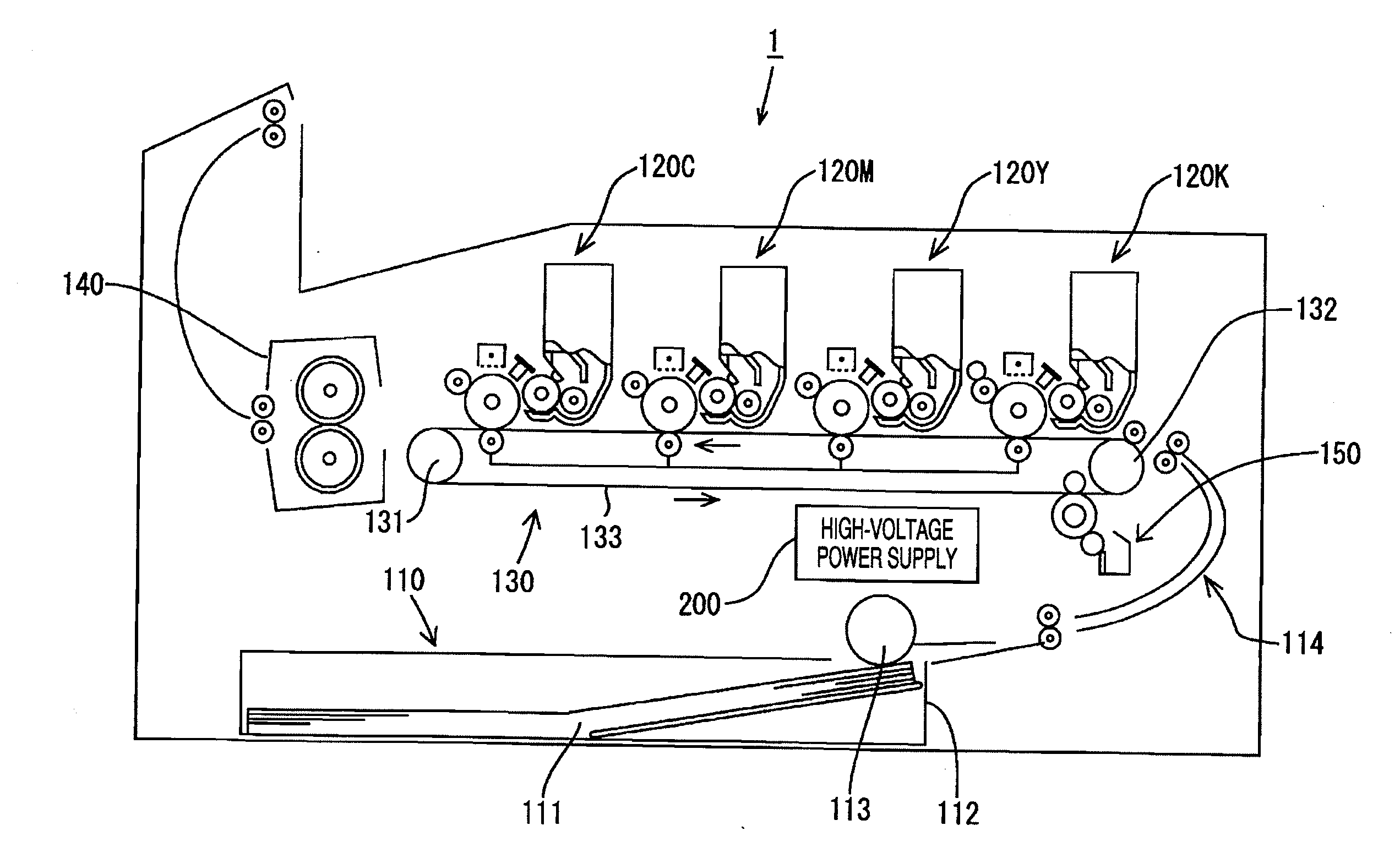
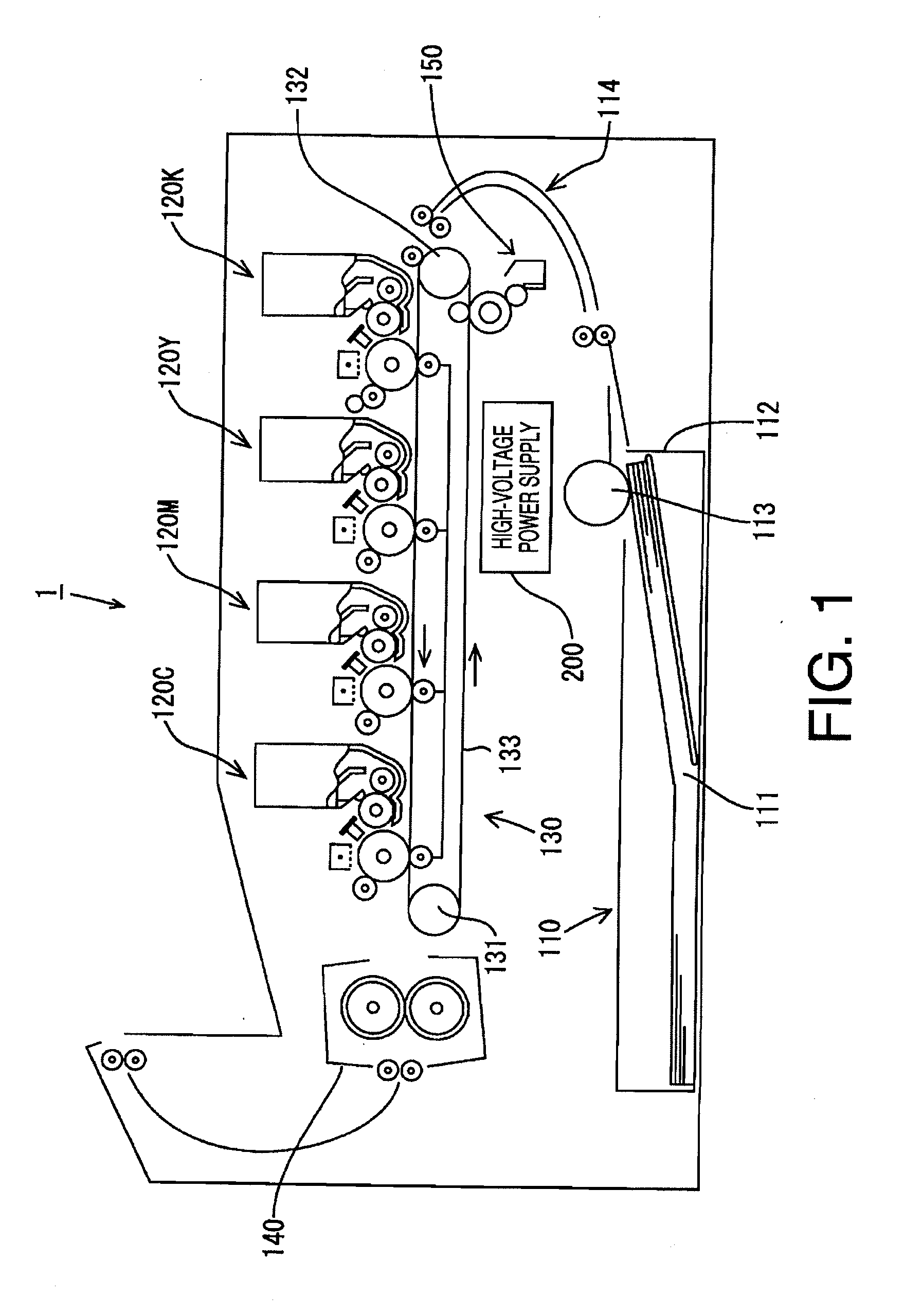
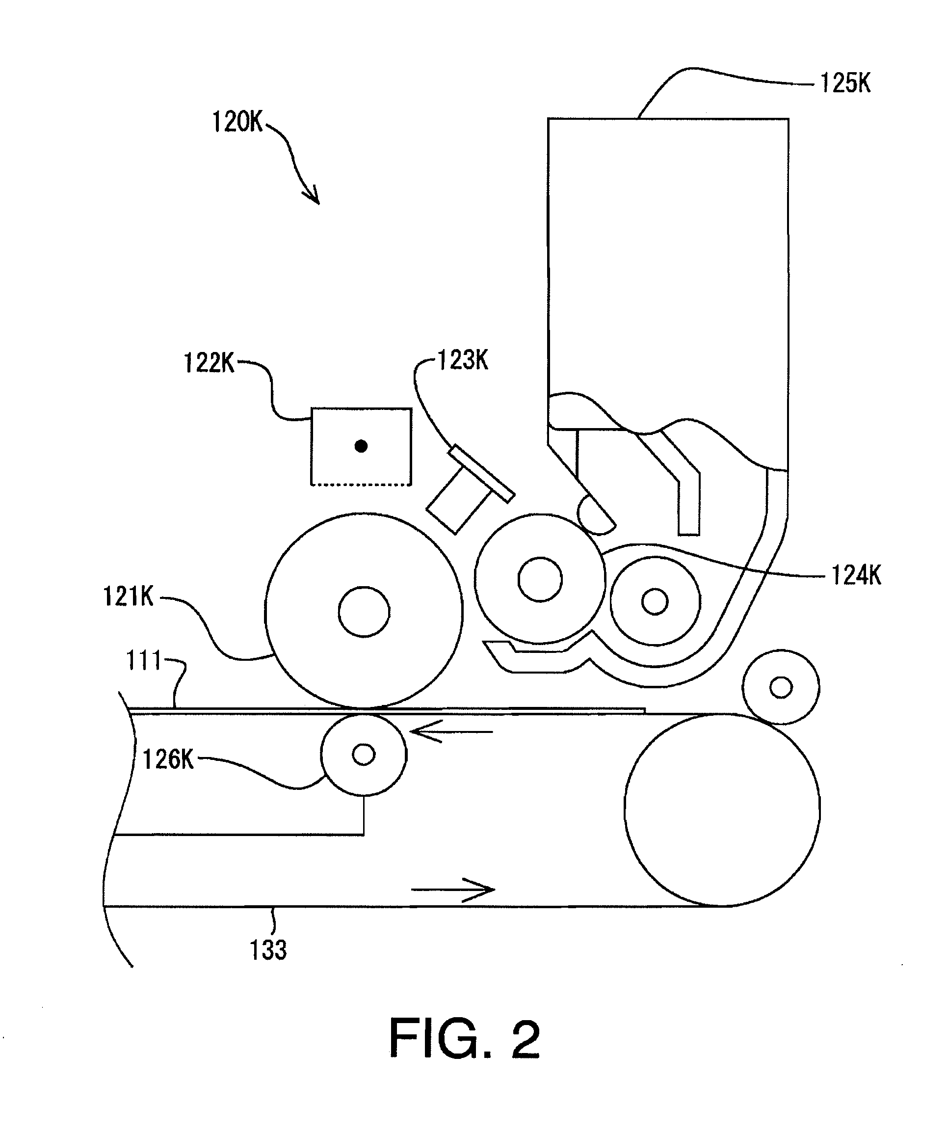
[0038]FIG. 3 shows the configuration of a charging mechanism and a power supply in accordance with the present invention. The charging process (for the photosensitive drum 121K) is carried out by the charging unit 122K by electrically charging the surface of the photosensitive drum 121K (see FIG. 2) up to a positive electric potential (e.g. +700 V). The charging unit 122K includes a casing 122Kc, a charging wire 122Kw and a grid 122Kg which is placed at an opening of the casing 122Kc. The photosensitive drum 121K is frame-grounded (unshown) to a ground line (reference potential) of the printer 1.

[0039]The power supply (part of the high-voltage power supply 200 for supplying electric power to the charging unit 122K) includes a control circuit board 210 and a charging voltage generating circuit 220. The charging voltage generating circuit 220 is equipped with a PWM signal control circuit 221, a driving circuit 222, a booster circuit 223, a high voltage detecting circuit 224 and a grid...

second embodiment

[0076]The control system of the second embodiment includes a wire control unit 310a which controls the electric potential and electric current of the charging wire 122Kw and a grid control unit 310b which controls the grid potential. The wire control unit 310a and the grid control unit 310b are capable of executing the control independently of each other.

[0077]The wire control unit 310a is capable of executing the control in two control modes: a wire constant-current control mode and a wire constant-potential control mode. The wire constant-current control mode is the default control mode (initial setting). The wire constant-potential control mode is a control mode that is used when the electric potential of the charging wire 122Kw has exceeded a prescribed threshold value (e.g. 7 kV) due to contamination, etc. of the charging wire 122Kw. Whether the electric potential of the charging wire 122Kw has exceeded the threshold value or not is detected by a wire potential measuring unit 3...

third embodiment

[0110] described hereinafter, when the high-voltage power supply 200 is powered on, a delay of a rising period (i.e., a time period in which the grid current etc. reaches target values) is suppressed, while the spark discharge is well suppressed.

[0111]Hereinafter, the charging voltage control process according to the third embodiment, which is a modification of the first embodiment, will be described with reference to a flowchart shown in FIG. 11 and a chart shown in FIG. 12.

[0112]The charging voltage control process is initiated by the control unit 310 (on the control substrate 210) when the high-voltage power supply 200 is activated. Specifically, when the printer 1 is powered on, when an image formation request is input through the operation unit of the printer 1 or from an external device, or when the operational status of the printer 1 is changed from a power save mode to a normal operation mode, the bight-voltage power supply 200 is activated.

[0113]The control unit 310 control...


PUM


Abstract

An image formation device for forming an image on a print medium by an electrophotographic process comprises a photosensitive body on which a developer image to be transferred to the print medium is formed by the electrophotographic process including charging of the photosensitive body, a charging unit which includes a charging wire and a grid and thereby electrically charges the photosensitive body, a charging power unit which applies wire potential to the charging wire, a wire potential measuring unit which measures the wire potential, and a charging control unit which controls the amount of electric charge supplied from the charging unit to the photosensitive body by controlling the wire potential based on the wire potential measured by the wire potential measurement unit. The charging control unit includes a control range restricting unit which restricts a control range of the wire potential within a prescribed electric potential.

Description

CROSS-REFERENCE TO RELATED APPLICATION[0001]This application claims priority under 35 U.S.C. §119 from Japanese Patent Applications No. 2008-251836 filed on Sep. 29, 2008 and No. 2009-038927 filed on Feb. 23, 2009. The entire subject matter of the applications is incorporated herein by reference.BACKGROUND[0002]1. Technical Field[0003]The following description relates to an image formation device and an image formation method.[0004]2. Related Art[0005]An image formation device for forming an image on a print medium (e.g. paper) uses high-voltage electric power for various electrophotographic processes (steps) such as charging, exposure, development, image transfer and fixation. Among the processes, the charging process involves a problem in that the charging function of a charging unit for electrically charging a photosensitive body (e.g. photosensitive drum) is easily deteriorated by contamination (stains, oxidation) of a charging wire of the charging unit. In a conventional techno...

Claims


Application Information

Patent Timeline
Patent Type & Authority Applications(United States)
IPC IPC(8): G03G15/02
CPCG03G15/0266G03G15/0291G03G2215/027
Inventor INUKAI, KATSUMITAKAHASHI, MASAMITSU
Owner BROTHER KOGYO KK
Why Eureka
Try Eureka