
Friction Stir Welding Tool and Weld Metal Structure with Plural Onion Rings

a technology of welding tool and onion ring, which is applied in the direction of manufacturing tools, welding devices, soldering devices, etc., can solve the problems of reducing welding strength, poor welding effect and reduction strength, and tool head likely to fracture, so as to enhance the strength of weld metal structure, improve horizontal stirring and mixing effect, and avoid the formation of defects on the weld metal structure

Inactive Publication Date: 2010-04-01
AEROSPACE INDUSTRIAL DEVELOPMENT CORPORATION
View PDF3 Cites 30 Cited by
  • Summary
  • Abstract
  • Description
  • Claims
  • Application Information

AI Technical Summary

Benefits of technology

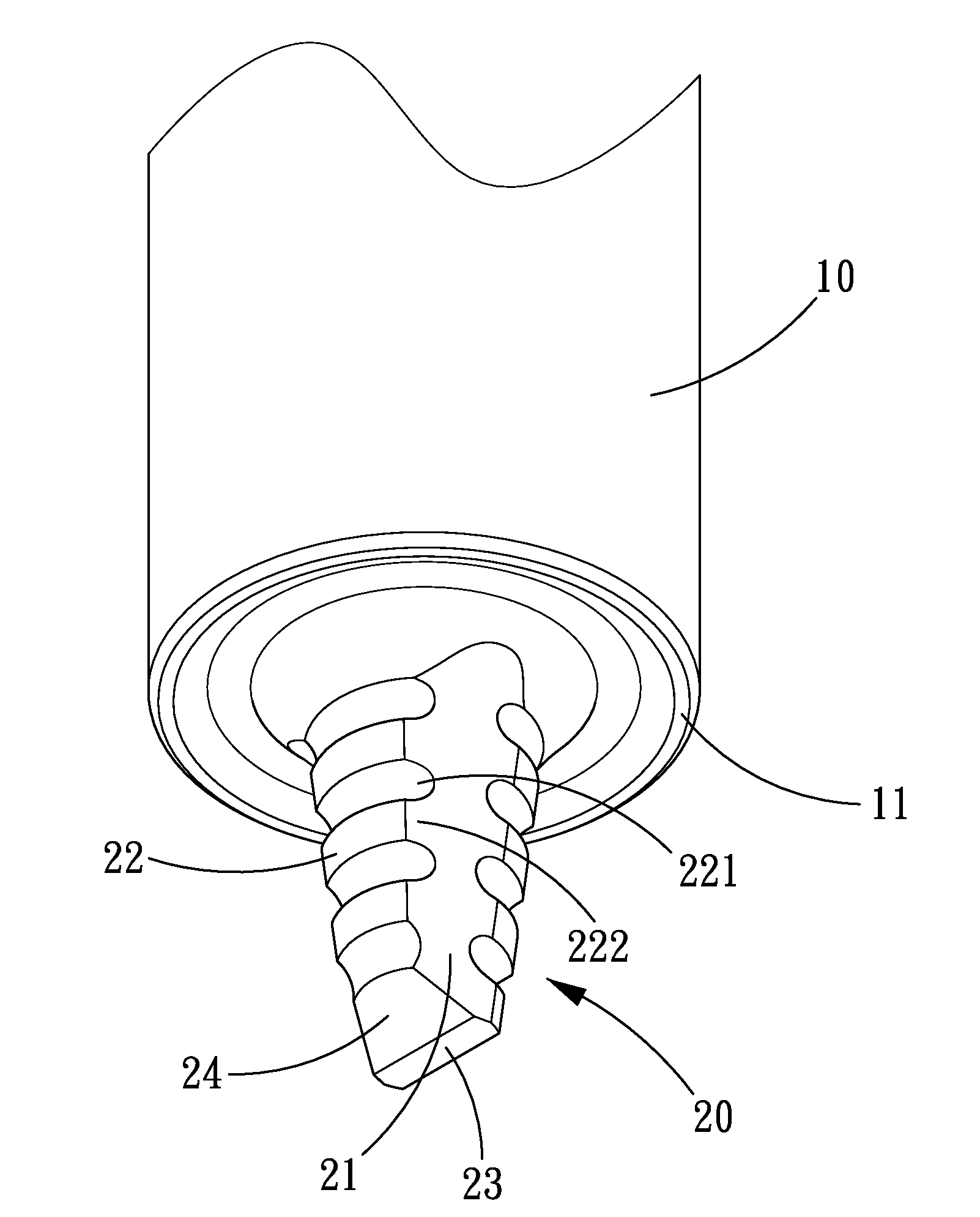
[0012]The primary objective of the present invention is to provide a friction stir welding tool which can produce plural onion rings on a weld metal structure formed by welding two metals and improve the horizontal stirring and mixing effect to enhance the strength of the weld metal structure formed by the two metals and avoid the defect formation on the weld metal structure.
[0013]In order to achieve the above objectives, the tool of the present invention is in a conical shape, and the tool head is axially formed on an outer periphery thereof with three surfaces and three spaced surfaces, and the biggest one in the three surfaces is a deviation cutting surface, the central axis of the tool head deviates from the central axis of the tool handle to become eccentric, and the three surfaces and three spaced surfaces are alternately arranged in such a manner that the respective spaced surfaces are located between each pair of surfaces, the respective spaced surfaces are formed with plural notches and plural protrusions that are alternately arranged in an axial direction of the tool head. By such arrangements, the tool head can utilize the three surfaces to stir the metals to improve the mixing effect, and the protrusions of the spaced surfaces together with the notches will produce a local material flow to stir the metals to produce a corresponding number of onion rings, so as to shorten the material backfill path of the respective onion rings to avoid occurrence of defect in the stirred zone.
[0014]The secondary objective of the present invention is to provide a friction stir weld metal structure with plural onion rings which is formed by welding two metals in a friction stir welding manner. The weld metal structure is formed with plural onion rings in the stirred zone with the number corresponding to the number of the protrusions and notches of each spaced surface of the tool head. By such arrangements, on a single weld metal structure, with the increase of the number of the onion rings, the size of the respective onion rings is correspondingly reduced, thus shortening the material backfill path of the respective onion rings to avoid the occurrence of defect.

Problems solved by technology

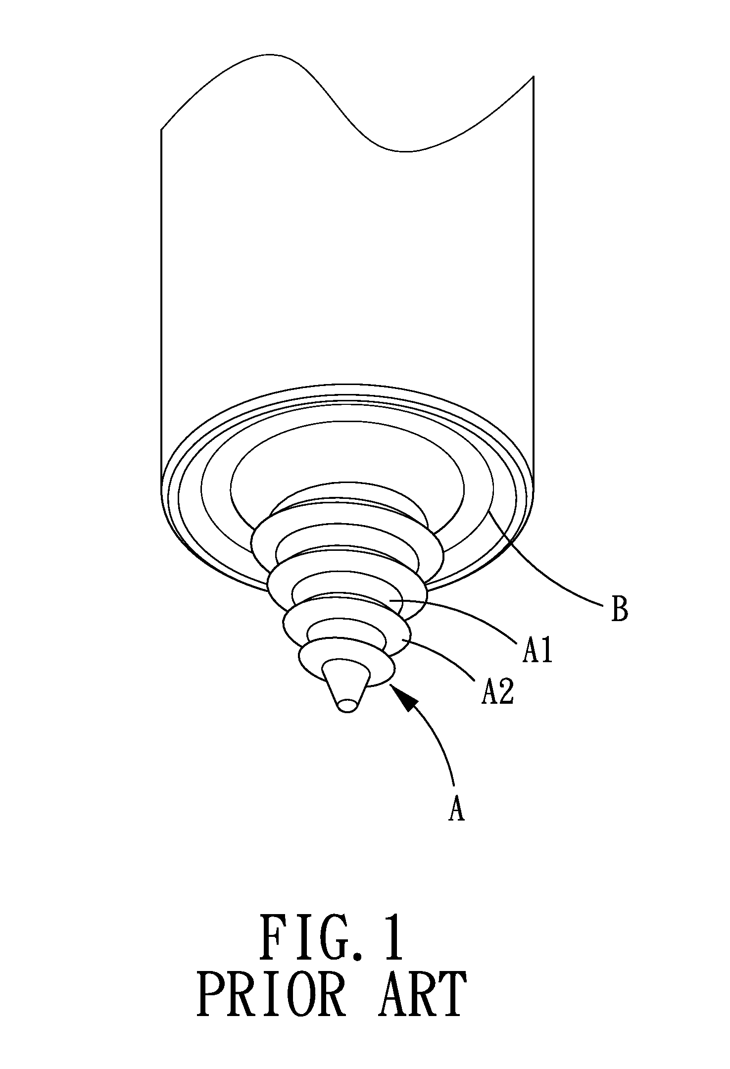
Moreover, since the tool head is round, the phenomena that the tool head cannot substantially stir and mix the two metals is likely to occur, so that the two metals can only be jointed after cooling under the reduced yield strength condition, thus causing poor welding effect and reduced strength.
After the above technology was put into practice for a certain period of time, it was found that if the tool head performs the friction stir welding operation vertically with respect to the two metals, the tool head is likely to fracture due to over-large resistance.
However, it can be found that the existing technology still suffers from the following problems.
Moreover, since the tool head A is formed in a conical shape, the horizontal stirring and mixing effect of the tool head A is still poor.
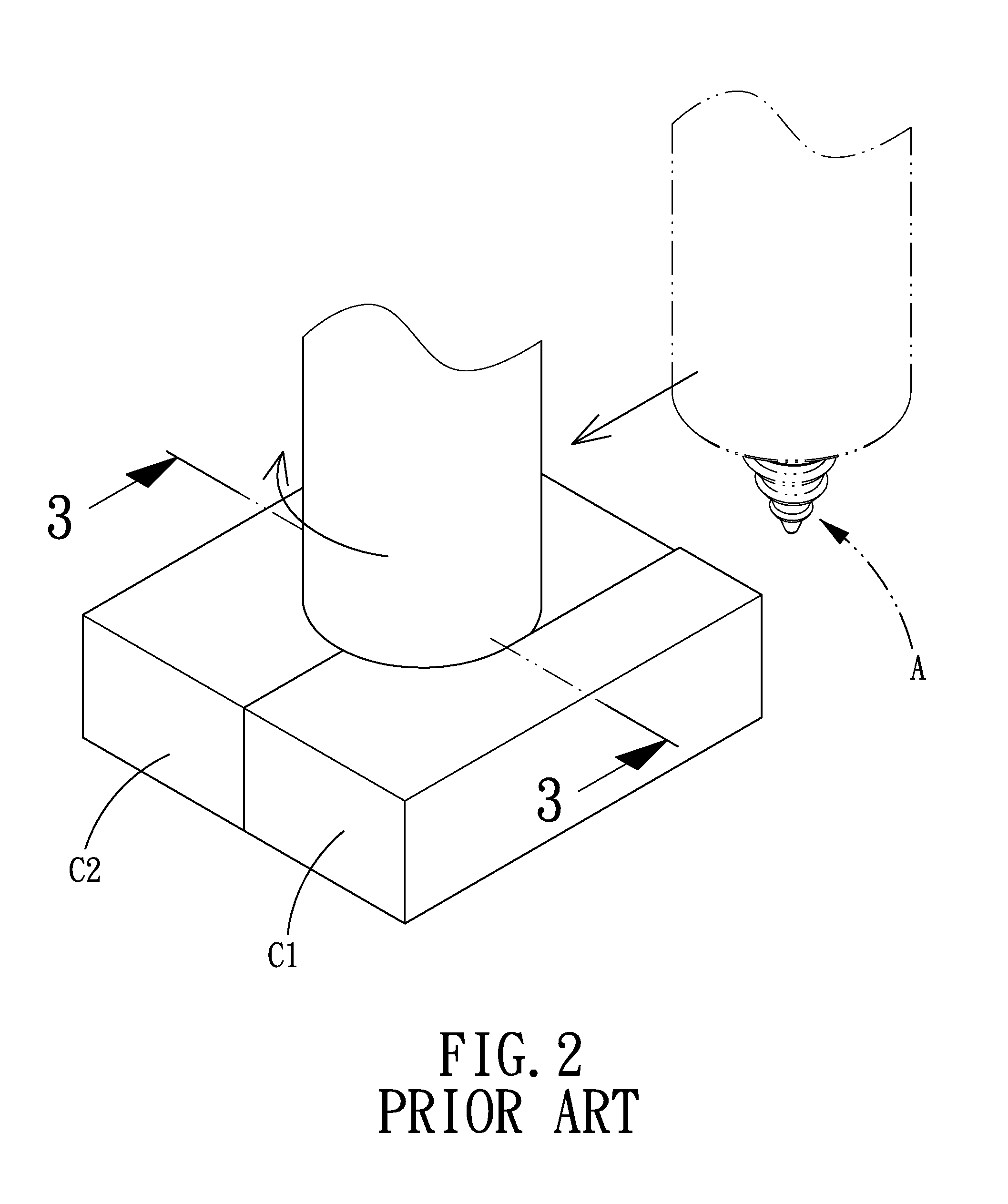
If the defect C is to be avoided, it is necessary to adjust the rotation speed, the forward feeding speed, the length and many other variables of the tool head A, and after a laborious trial-and-error process, the formation of the defect C4 could be gradually reduced, yet, the defect might not be completely eliminated for certain plate thickness, thus wasting time, labor and material.

Method used


Image

  • Friction Stir Welding Tool and Weld Metal Structure with Plural Onion Rings
  • Friction Stir Welding Tool and Weld Metal Structure with Plural Onion Rings
  • Friction Stir Welding Tool and Weld Metal Structure with Plural Onion Rings

Examples


Embodiment Construction

[0029]The present invention will be clearer from the following description when viewed together with the accompanying drawings, which show, for purpose of illustrations only, the preferred embodiment in accordance with the present invention.

[0030]Referring to FIGS. 7-9, a friction stir welding tool in accordance with the present invention comprises a tool handle 10 and a tool head 20.

[0031]The tool handle 10 has one end formed with a shoulder 11 on a periphery thereof. The shoulder 11 is provided with an annular shoulder groove 110 around a central axis O of the tool handle 10, and a curved protruding shoulder connecting portion 111 at an inner side of the annular shoulder groove 110.

[0032]The tool head 20 is in a conical shape and formed at the end of the tool handle 10 and connected to the shoulder connecting portion 111. The tool head 20 has an eccentrical axis O1 deviating from the central axis O of the tool handle 10. The tool head 20 is axially formed on an outer periphery the...


PUM

PropertyMeasurementUnit
heightaaaaaaaaaa
thicknessaaaaaaaaaa
diameteraaaaaaaaaa

Abstract

A friction stir welding tool and weld metal structure with plural onion rings, in which the tool is formed on the tool head with three surfaces, which are connected to one another through three spaced surfaces. An eccentrical axis of the tool head deviates from a central axis of the tool handle. One of the three surfaces is a deviation cutting surface which is a flat surface formed by cutting off a wall thickness from one side of an outer peripheral surface of the tool head toward the central axis of the tool handle. Each of the three spaced surfaces is alternately formed with plural notches and plural protrusions. The above welding tool is used to perform a stir friction welding operation to two metals to form the weld metal structure with the same number of onion rings as the protrusions and notches of each of the spaced surfaces.

Description

[0001]This application is a continuation of part of U.S. patent application Ser. No. 12 / 238,841, which claims the benefit of the earlier filing date of Sep. 26, 2008. Claim 1 of this application is added with a new limitation than the previous Claim 1 of the U.S. patent application Ser. No. 12 / 238,841, Claim 2 of this application is added with a new limitation that the previous claim 2 of the U.S. patent application Ser. No. 12 / 238,841. Claims 3-5 of this application are the same as the previous claims 3-5 of the U.S. patent application Ser. No. 12 / 238,841, Claims 6-7 of this application are new, and Claim 8 of this application is revised from the previous claim 6 of the U.S. patent application Ser. No. 12 / 238,841.BACKGROUND OF THE INVENTION[0002]1. Field of the Invention[0003]The present invention relates to a friction stir welding technology, and more particularly to a friction stir welding tool and a weld metal structure with plural onion rings.[0004]2. Description of the Prior A...

Claims


Application Information

Patent Timeline
Patent Type & Authority Applications(United States)
IPC IPC(8): B32B15/01B23K20/12
CPCY10T428/12493B23K20/1255
Inventor AOH, JONG-NINGYEN, AN-CHENGTANG, TONYDONG, MING-TANGHWANG, BOBHUANG, JIN-FALIN, PAI-CHEN
Owner AEROSPACE INDUSTRIAL DEVELOPMENT CORPORATION
Learn More