
Variable rigidity vaginal dilator and use thereof

a vaginal dilator and variable rigidity technology, applied in the direction of dilators, surgery, etc., can solve the problem that no specific design is designed to allow the patient to control every aspect of the process

Active Publication Date: 2010-04-01
BORKON WILLIAM D
View PDF43 Cites 9 Cited by
  • Summary
  • Abstract
  • Description
  • Claims
  • Application Information

AI Technical Summary

Benefits of technology

[0012]The inflatable variable rigidity vaginal dilator of the present invention facilitates vaginal dilation and allows the patient complete control of the dilating process.

Problems solved by technology

Although several dilating devices exist, even inflatable devices, none is specifically designed to allow the patient to control every aspect of the process, in a safe, private, carefully graduated dilation program that is carried out in the patient's home.

Method used


Image

  • Variable rigidity vaginal dilator and use thereof
  • Variable rigidity vaginal dilator and use thereof
  • Variable rigidity vaginal dilator and use thereof

Examples


Embodiment Construction

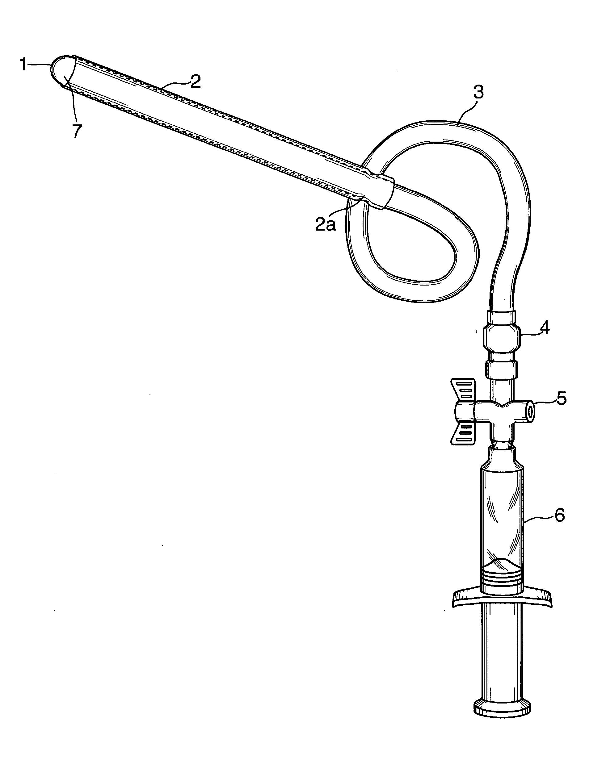
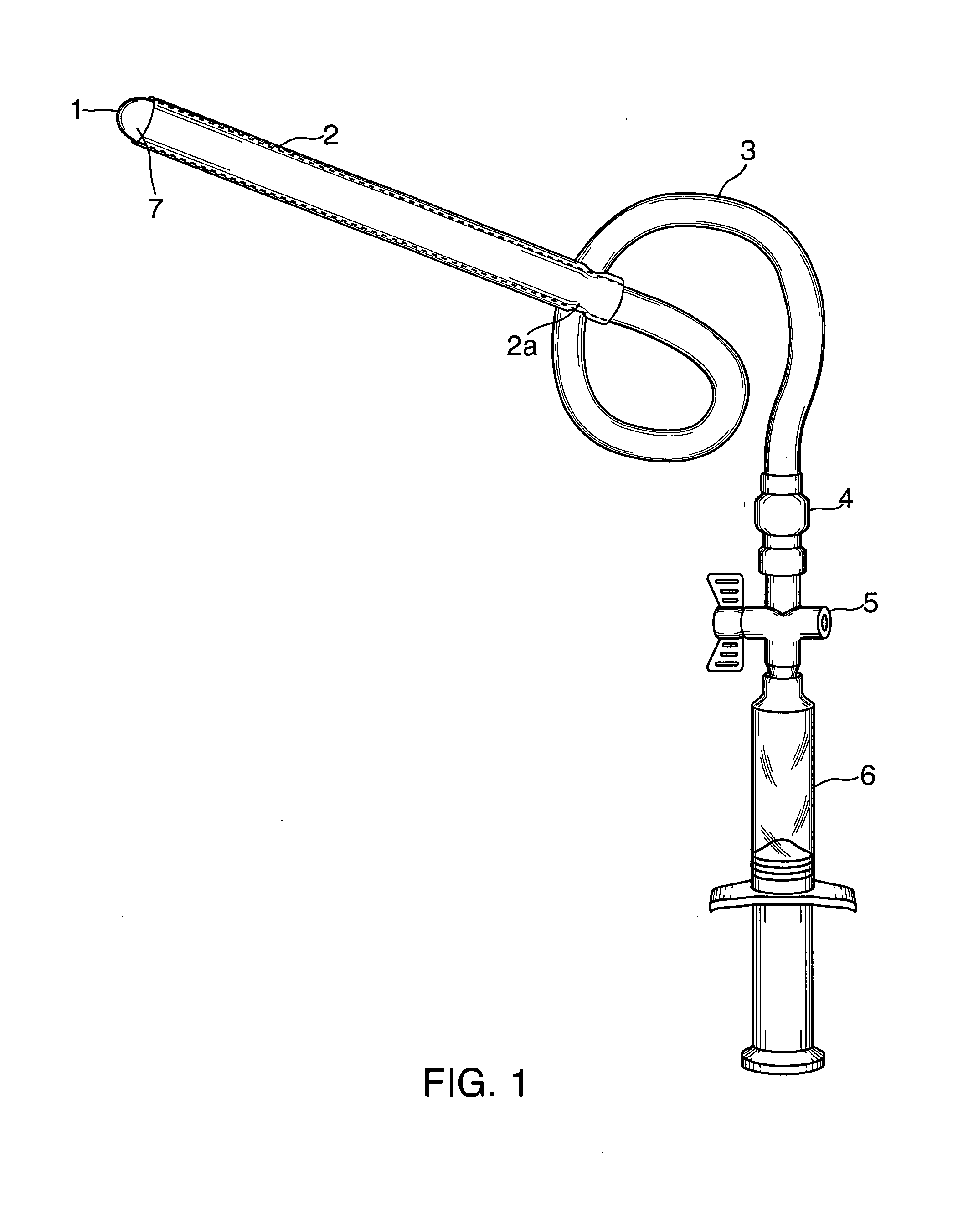
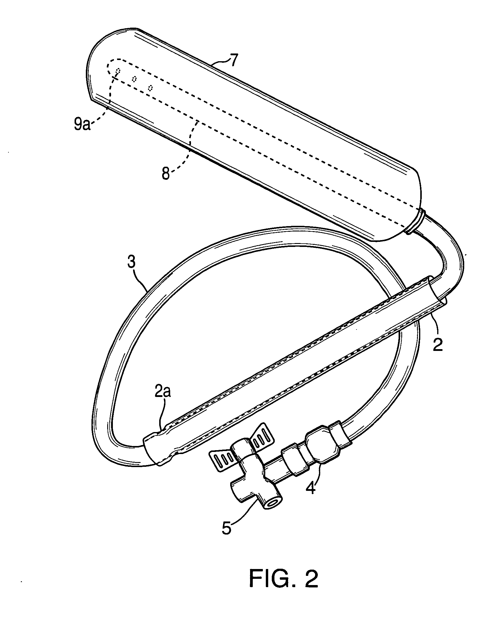
[0018]As shown in FIGS. 1 and 2, the variable rigidity vaginal dilating device of the present invention is comprised of a catheter 8 having a plurality of ports 9a, an inflatable member or balloon 7, a tubular member 3, a valve and stopcock 5, a syringe 6 or pump (not shown), and, optionally, an inline pressure gauge (not shown).

[0019]At least a portion of catheter 8 is disposed within inflatable balloon 7. Preferably, substantially all of catheter 8 is disposed within inflatable balloon 7. More preferably, all of catheter 8 is disposed within inflatable balloon 7.

[0020]One end of catheter 8 extends within balloon 7. The other end of catheter 8 is fixed to balloon 7 and to one end of tubular member 3, in a fluid (i.e. water and air) tight manner. The other end of tubular member 3 is fixed to a valve or stopcock 5, in a fluid (i.e. water and air) tight manner.

[0021]An air and liquid tight seal between tubular member 3 and stopcock 5 can suitably be obtained by means of a friction fit...


PUM


Abstract

Relatively pain free vaginal dilation is obtained by inserting into the vaginal canal a variable rigidity vaginal dilator having an inflatable balloon, in a manner that avoids insertion into the urethra. Air is introduced into the balloon. When the patient has gained confidence in the pain free use of the dilator, the balloon is deflated to remove the air and water is introduced into the balloon to expand it so that it contacts the vaginal canal and exerts a pressure thereon. This contact is maintained for a period of up to about 15 minutes. The pressure and / or contact time is stepwise sequentially increased to a maximum of about 12 atmospheres and a contact time of up to about 45 minutes, in accordance with a regimen and instructions established by the patient's healthcare provider and tailored to the patient's specific needs. A preferred embodiment of the dilator and a kit employing same, useful in the method of the invention, are disclosed.

Description

BACKGROUND OF THE INVENTION[0001]As the medical community begins to understand and treat Female Sexual Dysfunction (FSD) numerous treatments are emerging. Dyspareunia is one form of FSD. Dyspareunia is caused by many anatomic and psychological problems. Some of the anatomic problems include pelvic surgery, vaginal stenosis and atrophy associated with aging or hormonal changes, radiation, transgender surgery, congenital abnormalities, and numerous other vaginal diseases. Psychological issues such as rape, abuse, anxiety, pelvic pain syndromes, and even lack of basic sexual education, can all have a devastating affect on women wanting to engage in vaginal intercourse, and are even more common than the anatomic causes of pain.[0002]All of these causes, and others, are amenable to treatment by the vaginal dilation program of the present invention, such process being carefully designed for the individual patient by a therapist and / or physician.[0003]Vaginal dilators are known in the prio...

Claims


Application Information

Patent Timeline
IPC IPC(8): A61M29/02
CPCA61M29/02
Inventor BORKON, WILLIAM D.
Owner BORKON WILLIAM D
Learn More