Control device, control program, and control method

a control device and control program technology, applied in adaptive control, process and machine control, instruments, etc., can solve the problems of phase delay, narrow track pitch of storage medium, and difficult control of a head

Inactive Publication Date: 2010-04-01
TOSHIBA STORAGE DEVICE CORP
View PDF0 Cites 119 Cited by
  • Summary
  • Abstract
  • Description
  • Claims
  • Application Information

AI Technical Summary

Problems solved by technology

In recent years, with a high density of write data with respect to a storage medium in a disk device, such as a magnetic disk device, a track pitch of the storage medium has been narrowed, and control of a head has been difficult.
As a countermeasure with respect to the actuator resonance, a notch filter is generally inserted, but this causes a phase delay.
For this reason, it is difficult to configure a multi-stage, and it is difficult to apply the countermeasure to a complex system.
Further, when an analysis based on the error back-propagation method is performed, a calculation related to the analysis becomes extraordinarily complicated.
However, the control by the neural network as the complex system nonlinear control as described above needs large CPU / DSP power to handle the sigmoid function instead of a power series as a computer.
Further, when a neural network having high usability is formed, nodes and links of an input layer and a hidden layer need to be increased, which results in increasing a calculation load.
However, a large amount of time and cost are required to form a dedicated IC.

Method used


Image

  • Control device, control program, and control method
  • Control device, control program, and control method
  • Control device, control program, and control method

Examples


first embodiment

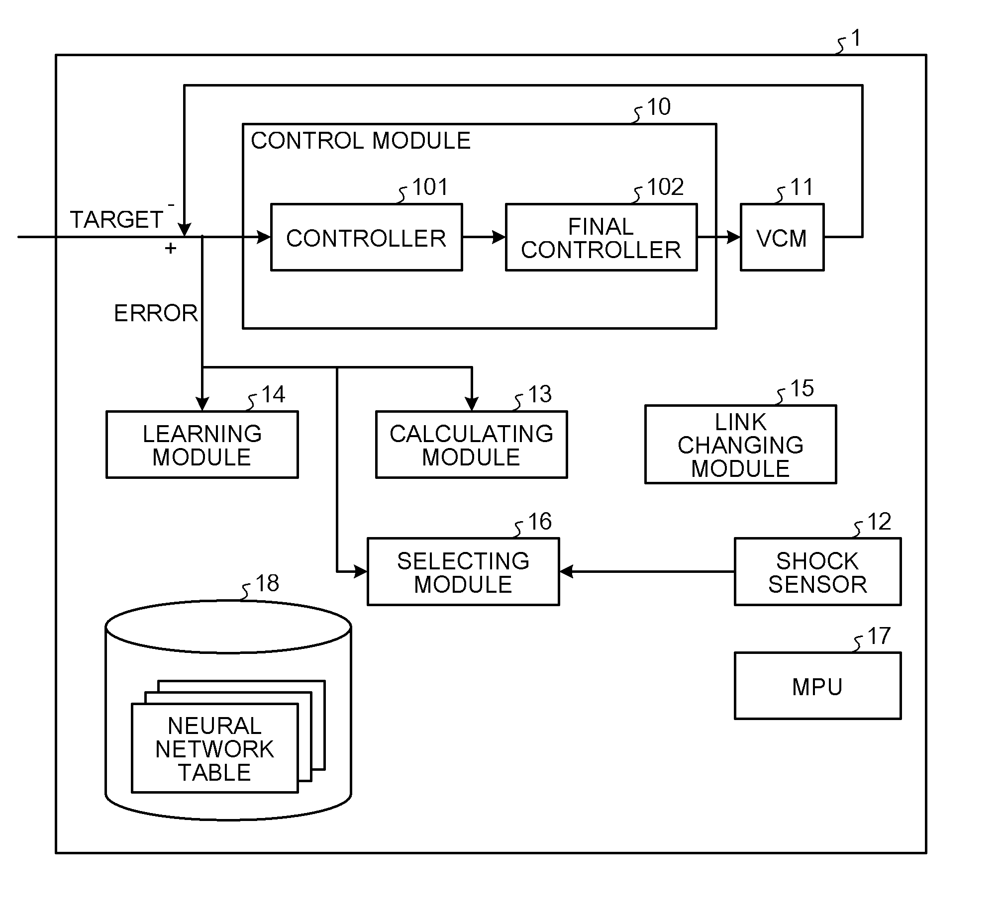
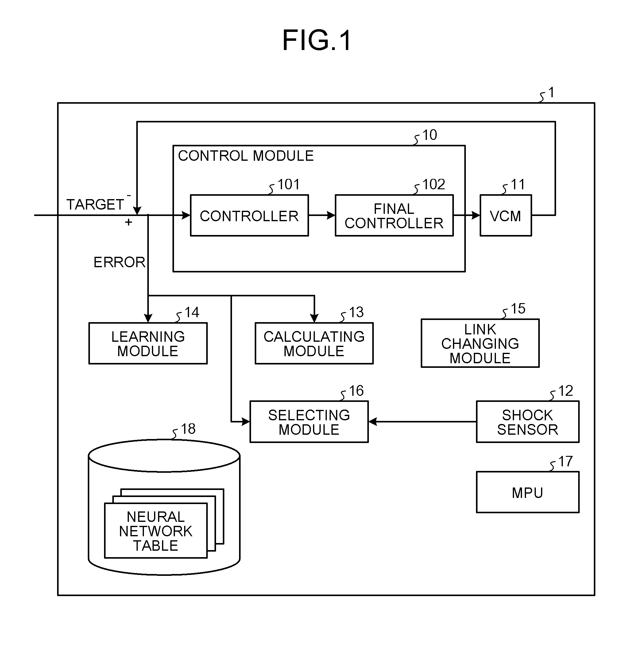
[0040]FIG. 1 is a block diagram of a disk device according to a first embodiment of the invention. As illustrated in FIG. 1, a disk device 1 (control device) according to this embodiment comprises a control module 10, a voice coil motor (VCM) 11, a shock sensor 12 (detecting module), a calculating module 13 (control module), a learning module 14 (a weight correcting module and a control error measuring module), a link changing module 15 (a link excluding module and a link introducing module), a selecting module 16 (a first selecting module, a second selecting module, an associating module, and a control error measuring module), a micro processing unit (MPU) 17, and a storage medium 18.

[0041]The VCM 11 that is a control object in this embodiment drives a magnetic head (not illustrated). The control module 10 comprises a controller 101 that controls the VCM 11 serving as the control object and a final controller 102 that adds a correction by a neural network to the control amount by t...

second embodiment

[0072]In the first embodiment, a function value based on the sigmoid function as the logistic function in the neural network is calculated, if necessary. However, in a second embodiment of the invention, a function value based on a sigmoid function and a derived function thereof is configured in a form of a look-up table. In this point, the second embodiment is different from the first embodiment. The description of the similar configuration and operation as those in the first embodiment will be omitted. FIG. 9 is a diagram of a look-up table of a sigmoid function. FIG. 10 is a diagram of a look-up table of a derived function of a sigmoid function.

[0073]The look-up table illustrated in FIGS. 9 and 10 is a table where values (function values) previously calculated with respect to a sigmoid function and a derived function thereof are associated with input values x, and is stored in the storage medium 18 in advance and managed. The calculating module 13 in the disk device 1 of the seco...

third embodiment

[0074]In the first and second embodiments, the disturbance is detected by one shock sensor 12, and the neural network table is selected on the basis of the magnitude and frequency of the detected disturbance. Meanwhile, a third embodiment of the invention is different from the first and second embodiments in that the shock sensor 12 is configured by a plurality of shock sensors (sensors A and B), and the neural network table is selected on the basis of parameters of a plurality of disturbances obtained by the shock sensor 12. Hereinafter, the configuration and operation that are different from those in the first and second embodiments will be described. FIG. 11 is a diagram of a classification table. FIG. 12 is a flowchart of the operation of a switching process in the third embodiment. FIG. 13 is a diagram of a changed classification table.

[0075]In the disk device 1 of the third embodiment, the shock sensor 12 is configured by the sensors A and B, as described above. As a table use...


PUM


Abstract

According to one embodiment, a control device that controls operation of a system includes a first selecting module, a second selecting module, a control error measuring module, a determining module, and a control module. The first selecting module selects a first neural network from neural networks different in network configuration from each other. The second selecting module selects a second neural network different from the first neural network from the neural networks. The control error measuring module measures first control error in control by the first neural network and second control error in control by the second neural network. The determining module compares the first control error and the second control error measured by the control error measuring module, and determines a neural network with less control error. The control module controls the operation of the system by the neural network with less control error determined by the determining module.

Description

CROSS-REFERENCE TO RELATED APPLICATIONS[0001]This application is based upon and claims the benefit of priority from Japanese Patent Application No. 2008-256376, filed on Oct. 1, 2008, the entire contents of which are incorporated herein by reference.BACKGROUND[0002]1. Field[0003]One embodiment of the invention relates to a control technology using a neural network.[0004]2. Description of the Related Art[0005]In recent years, with a high density of write data with respect to a storage medium in a disk device, such as a magnetic disk device, a track pitch of the storage medium has been narrowed, and control of a head has been difficult. Further, as a control frequency and request density in the disk device have been increased, an influence due to a separation between required control and control based on a basic control model by actuator resonance has been increased. As a countermeasure with respect to the actuator resonance, a notch filter is generally inserted, but this causes a pha...

Claims


Application Information

Patent Timeline
Patent Type & Authority Applications(United States)
IPC IPC(8): G05B9/03G06N3/02
CPCG06N3/0454G05B13/027G06N3/045
Inventor MATSUSHITA, HIROKI
Owner TOSHIBA STORAGE DEVICE CORP
Why Eureka
Try Eureka