Methods for Linking Motor Vehicles to Reduce Aerodynamic Drag and Improve Fuel Economy

Inactive Publication Date: 2010-04-01
KRONENBERG DAVID
View PDF66 Cites 32 Cited by
  • Summary
  • Abstract
  • Description
  • Claims
  • Application Information

AI Technical Summary

Benefits of technology

[0016]Once the mechanical linkage is formed, the linking system allows the driver of the leading vehicle to monitor and control the essential functions of the trailing vehicle, such as throttle, brakes, gearing, signal indicator, etc. As a result, the driver of the leading vehicle operates the driving mechanisms of both the leading and trailing vehicles. In another embodiment, the linking system may also be used in a towing operation where the operation of the trailing vehicle is substantially deactivated.
[0017]The dynamic linkage between the leading and trailing vehicles may be disconnected by either driver as desired, especially when the operation conditions require individual manipulation of the vehicles such as in tight corners and weight stations or during emergency maneuvers. To disconnect, either driver may operate the control unit of the linking system to remove the arm of the active member from the receiving area of the passive member. Because both vehicles may still be fully operational at the time of disconnection, the drivers of both vehicles may continue their individual operation of the vehicle with minimum delay.
[0018]The disclosed method may also allow the linking of the leading and trailing vehicles while they are in motion. In order to accomplish this, the linking system is designed so that the leading and trailing vehicles do not need to be in perfect alignment when the mechanical connection therebetween is established. As a result, the linkage may be formed in motion when the speeds of the vehicles are moderate and the drivers of the vehicles are reasonably skilled in the linking process. Specifically, in a fully automated embodiment, the control unit is activated when the leading and trailing vehicles are in alignment and within an appropriate range, e.g. less than 100 meters. The control unit then operates both vehicles' cruise control systems to gradually bring the vehicles together to a suitable distance for the formation of the dynamic linkage.
[0019]The linking system may be used in a fleet of vehicles to streamline their operation and improve their collective energy efficiency. For example, a fleet dispatcher may identify vehicles of the fleet with overlapping routes before dispatching those vehicles so that the drivers of the vehicles can be provided with the time and location of the scheduled linking. At the end of the overlapping route, the dispatcher may instruct the drivers to disconnect the linked vehicle so that the individual vehicles can pursue their separate destinations.

Problems solved by technology
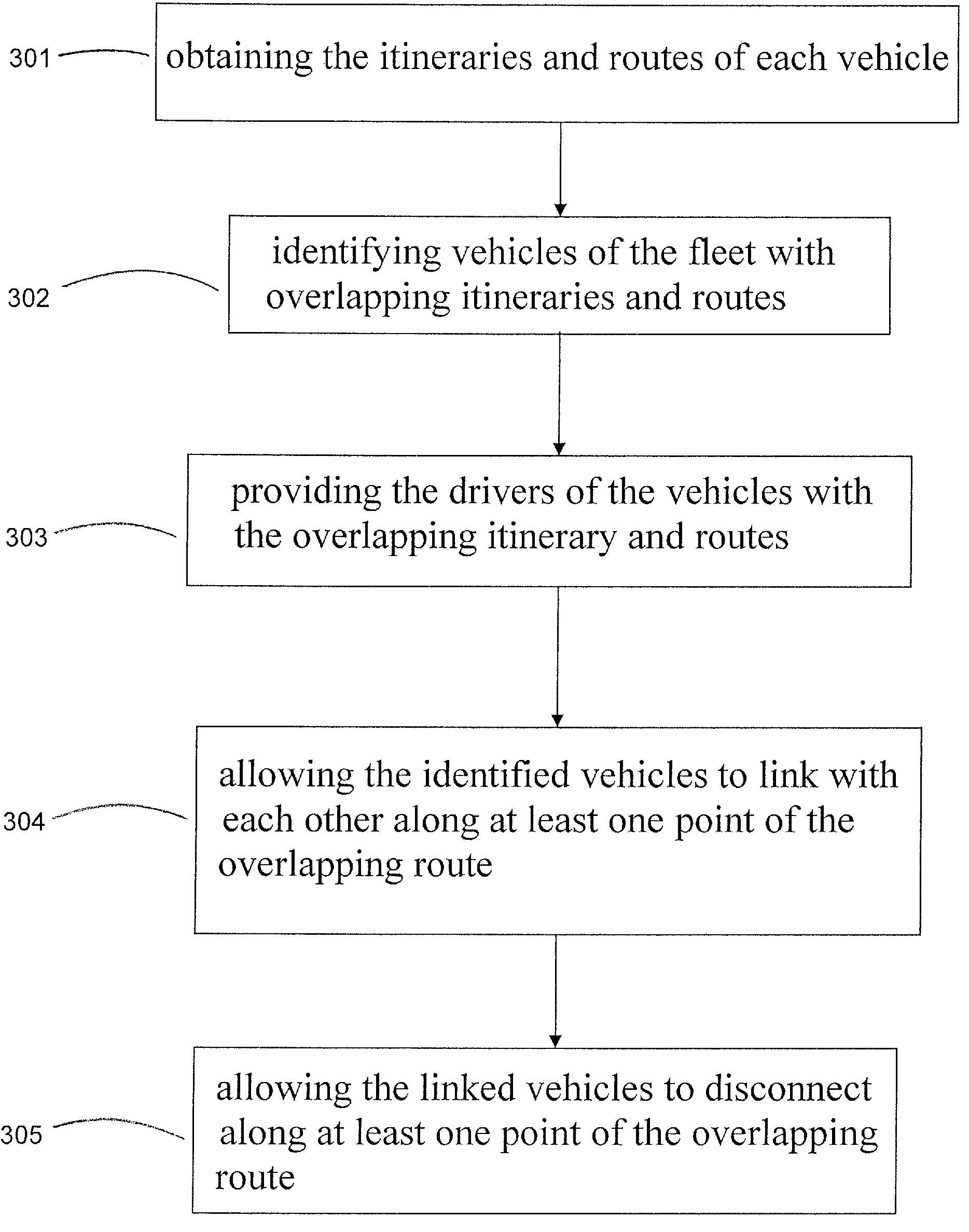
However, as the non-operating vehicles are almost completely deactivated during towing, none of the known linking devices or assemblies involves the use of an active (e.g. extendable-retractable) member on the trailing vehicle that engages with a passive member on the leading vehicle.
Nor is there a known linking mechanism purported to operate two or more motor vehicles to reduce their collective aerodynamic drag.
In addition, because the towed vehicles are generally deactivated during towing, the driving mechanisms of the towing vehicles, such as throttles, brakes, and gears, inevitably incur excessive wear and tear, which may adversely affect the overall performance and energy efficiency of the two connected vehicles.
However, the slave power source of the trailer may only operate to supplement the tractor and generally does not operate to drive the trailer alone without the tractor.

Method used


Image

  • Methods for Linking Motor Vehicles to Reduce Aerodynamic Drag and Improve Fuel Economy
  • Methods for Linking Motor Vehicles to Reduce Aerodynamic Drag and Improve Fuel Economy
  • Methods for Linking Motor Vehicles to Reduce Aerodynamic Drag and Improve Fuel Economy

Examples


Embodiment Construction

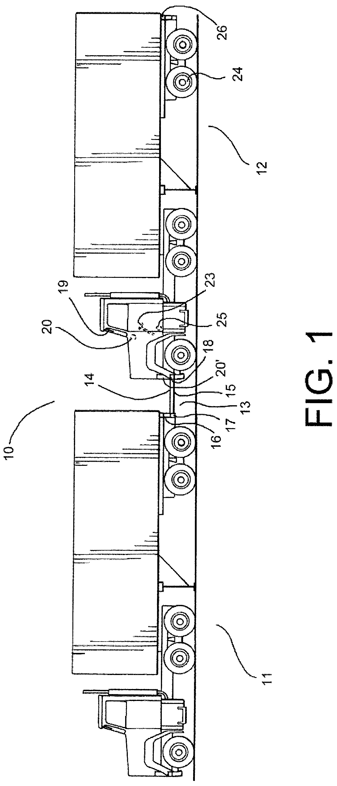
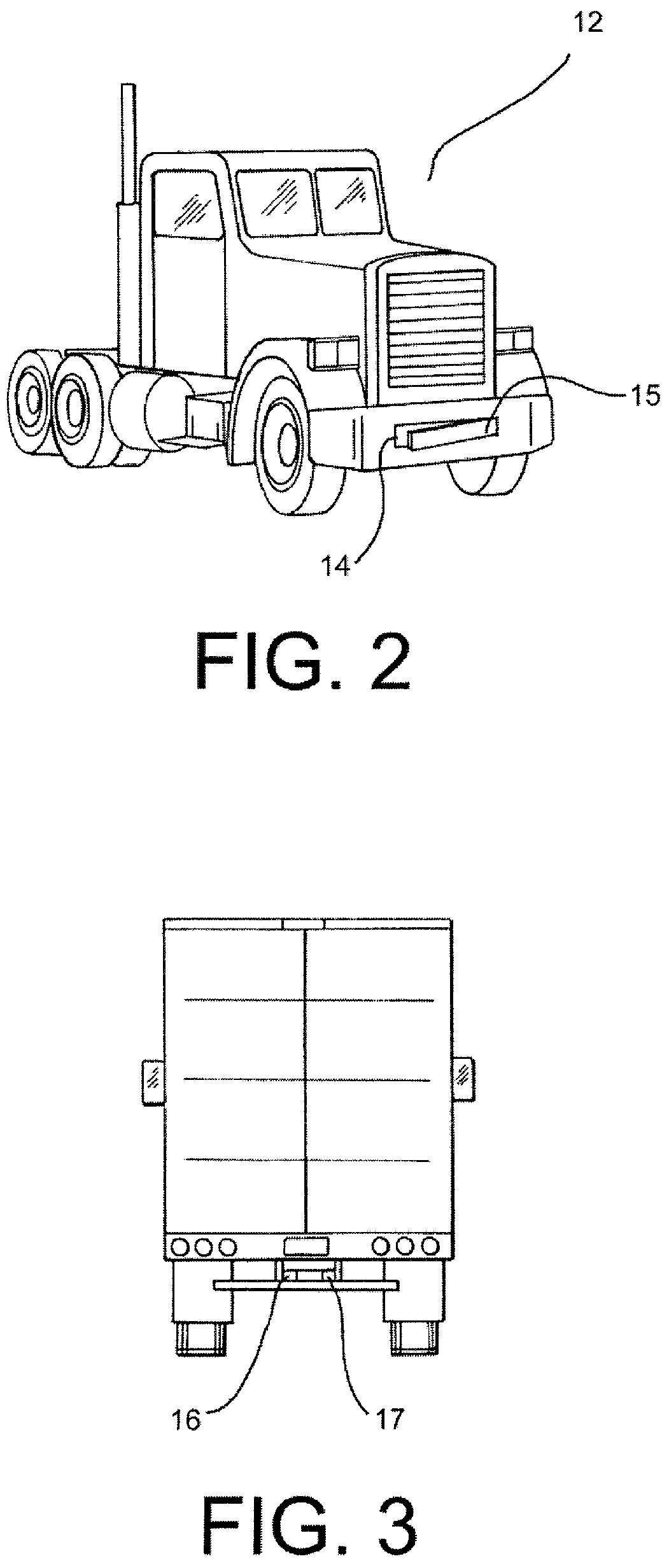
[0030]A system 10 for linking a leading vehicle 11 and a trailing vehicle 12 to reduce their collective aerodynamic drag is shown in FIG. 1. The system 10 may include a dynamic linking assembly 13 that comprises an active member 14 having an arm 15 positioned on the trailing vehicle 12, a passive member 16 having a receiving area 17 positioned on the leading vehicle 11, and a control unit 18 coupled to the active member 14 for monitoring and controlling the linking of the vehicles. In one embodiment, the arm 15 of the active member 14 may be extended, retracted, or otherwise positioned by the control unit 18. Although FIG. 1 illustrates the active member 14 as being positioned on the trailing vehicle 12 and the passive member 16 as being positioned on the leading vehicle 11, it is understood that they may also be positioned vice versa within the scope of this disclosure.

[0031]Although illustrated in FIG. 1 as “semis” or “tractor-trailer” trucks, the leading and trailing vehicles (11...


PUM


Abstract

Methods for linking two or more vehicles to achieve reduced aerodynamic drag while the vehicles are travelling on the road are disclosed. The disclosed methods utilize a dynamic linking system that not only physically connects the vehicles but also allows the driver of the leading vehicle to monitor and control essential functions of the trailing vehicles. Preferably, the driving mechanisms of the trailing vehicles, such as throttles, brakes, and gears, are fully operational so as not to put excessive burden on the driving mechanisms of the leading vehicle. Methods for linking individual vehicles as well as streamlining the operation of a fleet of vehicles are also disclosed.

Description

BACKGROUND[0001]1. Technical Field[0002]Methods for linking two or more vehicles to achieve reduced collective aerodynamic drag while the vehicles are travelling on the road are disclosed. The disclosed methods utilize a dynamic linking system that not only physically connects the vehicles but also allows the driver of the leading vehicle to monitor and control essential functions of the trailing vehicles. Preferably, the driving mechanisms of the trailing vehicles, such as throttles, brakes, and gears, are fully operational so as not to put excessive burden on the driving mechanisms of the leading vehicle. Methods for linking individual vehicles as well as streamlining the operation of a fleet of vehicles are also disclosed.[0003]2. Description of the Related Art[0004]A significant portion of the energy expended by motor vehicles is to overcome aerodynamic drag. In order to improve fuel economy and conserve energy, a wide variety of devices and methods have been developed in the ar...

Claims


Application Information

Patent Timeline
IPC IPC(8): G06F19/00B60D1/62
CPCB62D12/02B62D53/00B62D35/001
Inventor KRONENBERG, DAVID
Owner KRONENBERG DAVID
Why Eureka
Try Eureka