Non Grid-Tied Vehicle-SoIar Uninterruptable Power System

a power system and non-grid technology, applied in emergency power supply arrangements, dc-ac conversion without reversal, greenhouse gas reduction, etc., can solve the problems of uncontrollable output, high variability, and high cost of magnum energy systems, so as to eliminate a major installation cost, the effect of reducing the cost of installation and reducing the cost of operation

Active Publication Date: 2020-02-06
NETZERO V2G TECH LLC
View PDF3 Cites 3 Cited by
  • Summary
  • Abstract
  • Description
  • Claims
  • Application Information

AI Technical Summary

Benefits of technology

[0028]In this way the system can use grid power to supplement solar power to keep the vehicle charged and maintain critical household services such as refrigeration, microwave cooking, and essential lighting as long as grid power is available. In the event of an outage, the stationary battery and the vehicle battery provide significant capacity to maintain critical services overnight and through cloudy weather, while allowing whatever solar energy is generated to replenish the battery and maintain services indefinitely.
[0029]The system is self-contained, does not re

Problems solved by technology

The only available alternatives are multi port inverter systems, such as those supplied by Princeton Power Systems, Ideal Power or Pika Energy or battery-supported back up systems such as the Sunny Island system of SMA, and Magnum Energy Systems, both of which are quite expensive.
There is another problem with conventional grid-tied solar systems in that the utilities are beginning to disfavor them as a threat to their business and a destabilizing element in the grid.
Grid-tied solar systems can inject power at any time, and their output is uncontrollable and highly variable.
As a result consumers who want the benefits of solar energy are not able to obtain permits to net meter from their local Electric Distribution Co

Method used


Image

  • Non Grid-Tied Vehicle-SoIar Uninterruptable Power System
  • Non Grid-Tied Vehicle-SoIar Uninterruptable Power System
  • Non Grid-Tied Vehicle-SoIar Uninterruptable Power System

Examples


example

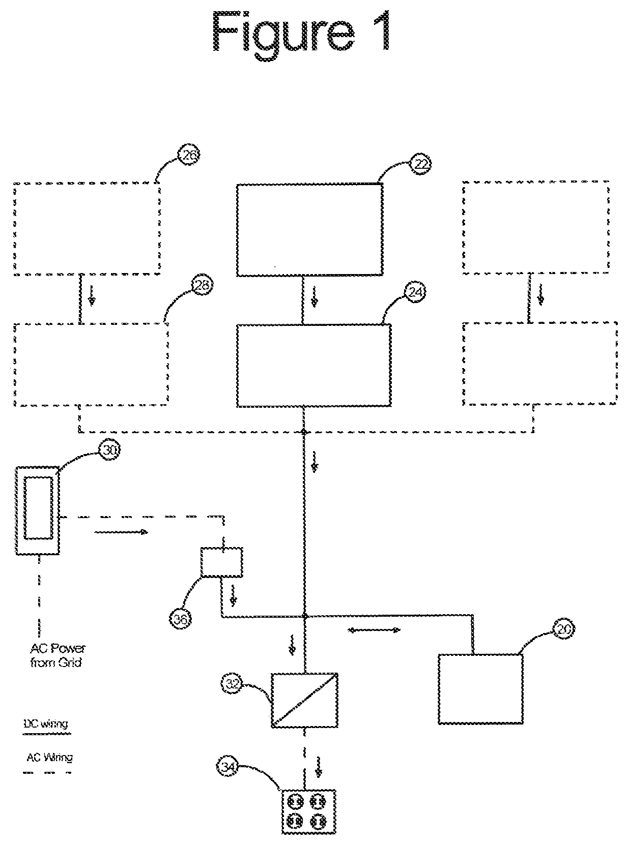
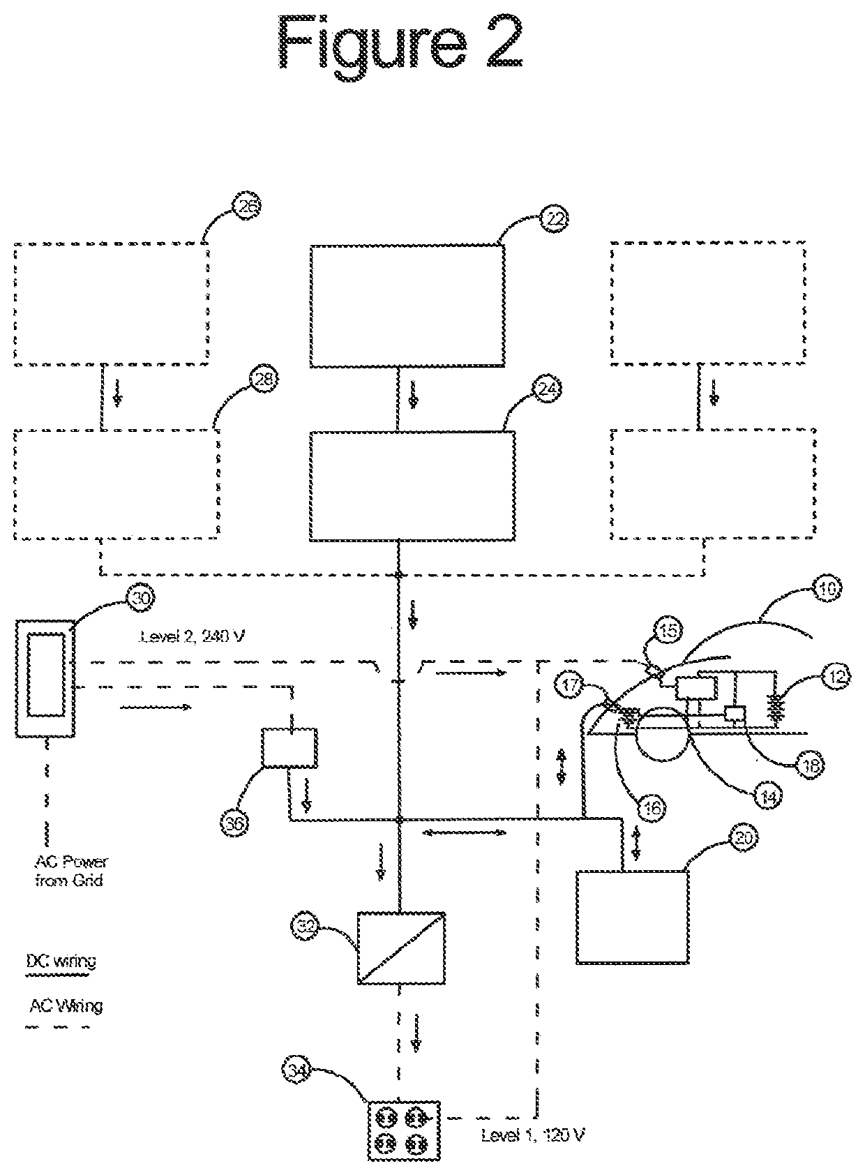
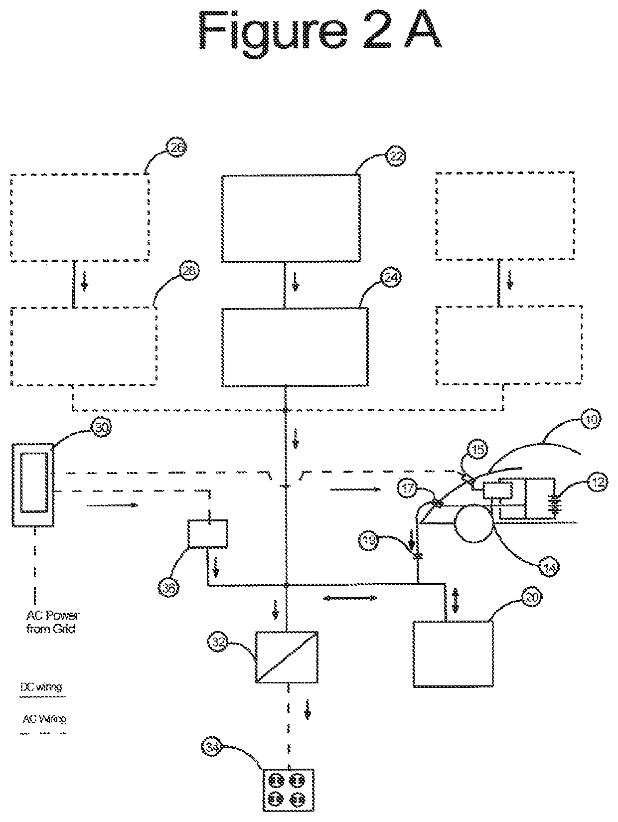
[0048]An installation similar to FIG. 2 has been built and tested. The basic components of the installation are shown schematically in FIG. 3 along with instrumentation inputs to permit measurement of key operating parameters. A single 200 Watt 36 Volt solar panel provided 12 V power through a Solar Boost 154i battery charge controller to the DC node. A 20 Amp fuse and a 100 Amp / 50 MV shunt provided safety and measurement of solar input.

[0049]120 V AC power from a sub panel in the Penn State University GridSTAR Solar Training Center at the Philadelphia Navy Yard was fed to the 30 Amp. battery charger, which was connected to the node through a 400 A, 50 mV shunt. The charger was a simple rectifier, which put out a voltage higher than the solar system. To allow the solar system to contribute, the charger input voltage was reduced by 20% through a buck transformer. The charger input was monitored by an AC current transformer putting out 5 V DC at 10 Amps AC.

[0050]The charger was connec...


PUM


Abstract

This invention is a DC-coupled, non grid-tied system comprising a solar panel, or an array of panels, a storage battery, a battery charger, an inverter, and optionally, a connection to an electric vehicle via both the regular AC charging connection and a DC connection. Unlike conventional grid-tied solar systems there is no possibility of solar or battery energy being fed back to the grid by virtue of the one-directional flow of energy through the battery chargers. The system can utilize all of the energy produced by the solar panels to provide power to critical household loads by storing electric energy in the storage battery. In the event of a grid outage, the system maintains power to the critical loads to the limits of the capacity of the batteries and the inverter, supplemented by whatever solar power is available. The energy available in an outage can be supplemented by using the main propulsion battery of an electric vehicle. The DC connection to the electric vehicle can be either indirect through the low voltage accessory system of the vehicle or direct through a high voltage quick charge port on the vehicle.

Description

CROSS-REFERENCE TO RELATED APPLICATIONS[0001]This application is related to U.S. patent application “Vehicle-Solar-Grid Integration” Ser. No. 14 / 101,423 filed Dec. 10, 2013, now issued as U.S. Pat. No. 9,566,867, Feb. 14, 2017, by the present inventor, and Provisional patent applications “Bidirectional Power Electronic Interface” No. 61 / 889,067, filed Oct. 10, 2013, “Bidirectional Power Electronic Interface with Sustaining Power” 61 / 921,583, filed Dec. 30, 2013, “Vehicle-Solar-Grid Integration with Supplementary Battery” 62 / 050,819, filed Sep. 16, 2014, and “Low-Cost EVPV for Vehicle-Solar-Grid Integration”, 62 / 297,462, filed Feb. 19, 2016, “Minimum Cost EVPV for Vehicle-Solar-Grid Integration” 62 / 299,756, filed Feb. 25, 2016, later filed as nonprovisional patent application Ser. No. 15 / 441,484, Feb. 24, 2017, and “Vehicle-Solar-Grid Integration for Back up Power” 62 / 465,424 filed Mar. 1, 2017 by the present inventor now filed as a patent application and “Multiple Load Micro-Grid Im...

Claims


Application Information

Patent Timeline
IPC IPC(8): H02J9/06H02J7/35H02S40/38H02J3/38
CPCH02M7/44H02S40/38H02J7/35H02J3/383H02J9/062B60L53/51B60L53/53B60L55/00B60L53/57Y02E10/56Y02T10/70Y02T10/7072Y02T90/12Y04S10/126H02J9/061H02J7/342H02J2310/48Y02E60/00Y02E70/30Y02B10/10H02J3/38
Inventor KYDD, PAUL HARRIMAN
Owner NETZERO V2G TECH LLC
Why Eureka
Try Eureka