
Method For Data Reception In A Multi-Function Receiving Device

Inactive Publication Date: 2007-11-29
NOKIA CORP
View PDF12 Cites 13 Cited by
  • Summary
  • Abstract
  • Description
  • Claims
  • Application Information

AI Technical Summary

Benefits of technology

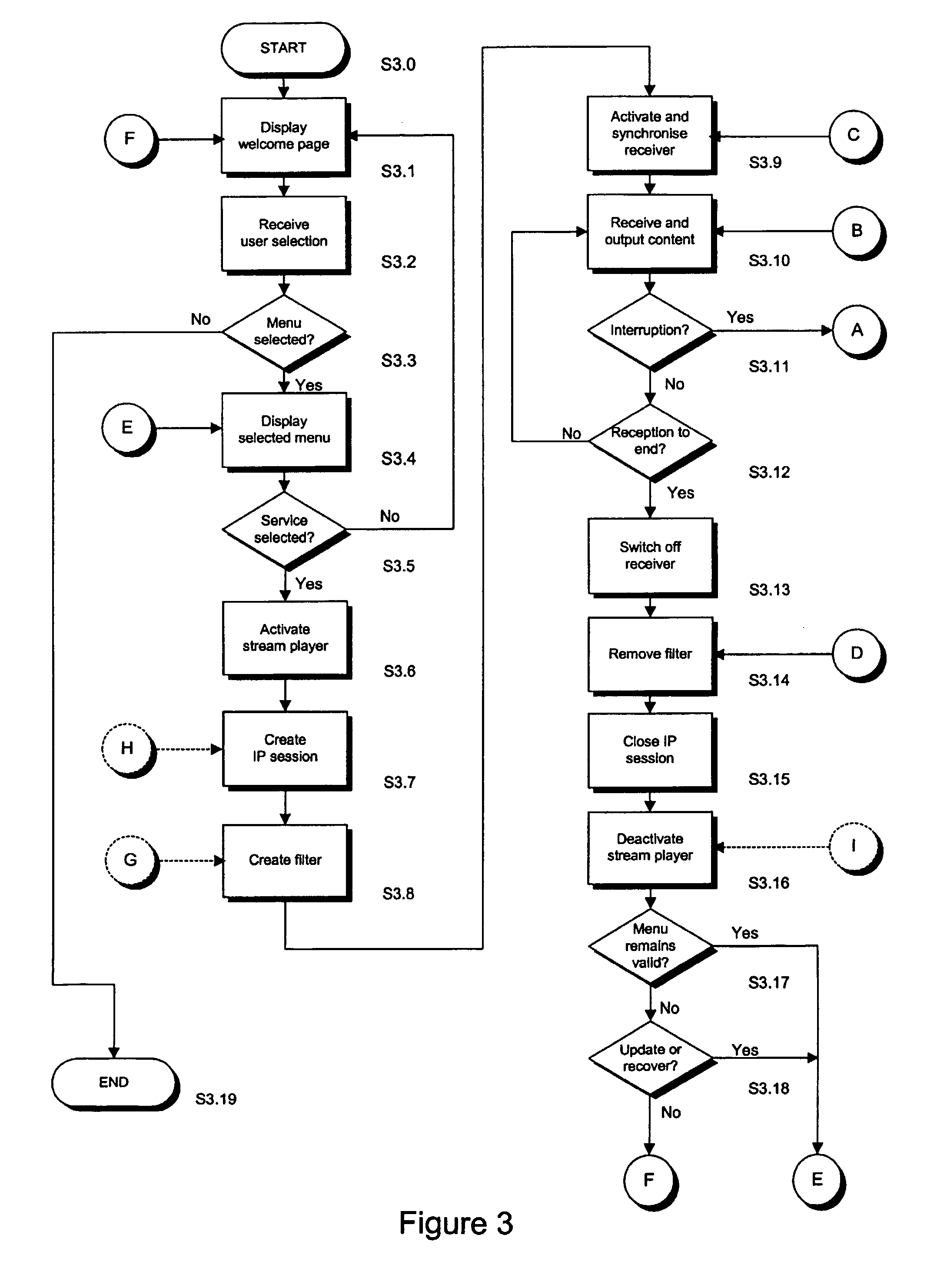
[0008] The data receiving may be configured to, after operating in said first resource saving mode for a first predetermined time period, operate in a second resource saving mode in which the receiving means is deactivated while the processing means and output means remain operational. The deactivation of the receiving means reduces demand placed on a source supplying power to the receiving means.

Problems solved by technology

However, a considerable amount of data is required to provide such services, and the reception and processing of this data may place significant demands on the restricted power and memory capacities of a mobile terminal.
However, the suspension of a service received from an external source is more problematical as the service itself is not interrupted and transmission of the data stream continues.
In this situation, a service receiving part of the mobile terminal may close down reception of the service but, should the user wish to return to the service, this may require data reception, processing and outputting applications to be set up and started again, causing delay and inconvenience.
This wastes power, particularly as a large proportion of the power consumption in such a mobile terminal is due to the demands of a receiver when receiving data transmissions, and may be problematical as mobile terminals are typically powered by a battery of limited capacity.
In addition, the reception and processing of data also requires processing resources, including memory, and prevent sufficient resources being available for handling the unrelated application.

Method used


Image

  • Method For Data Reception In A Multi-Function Receiving Device
  • Method For Data Reception In A Multi-Function Receiving Device
  • Method For Data Reception In A Multi-Function Receiving Device

Examples


Embodiment Construction

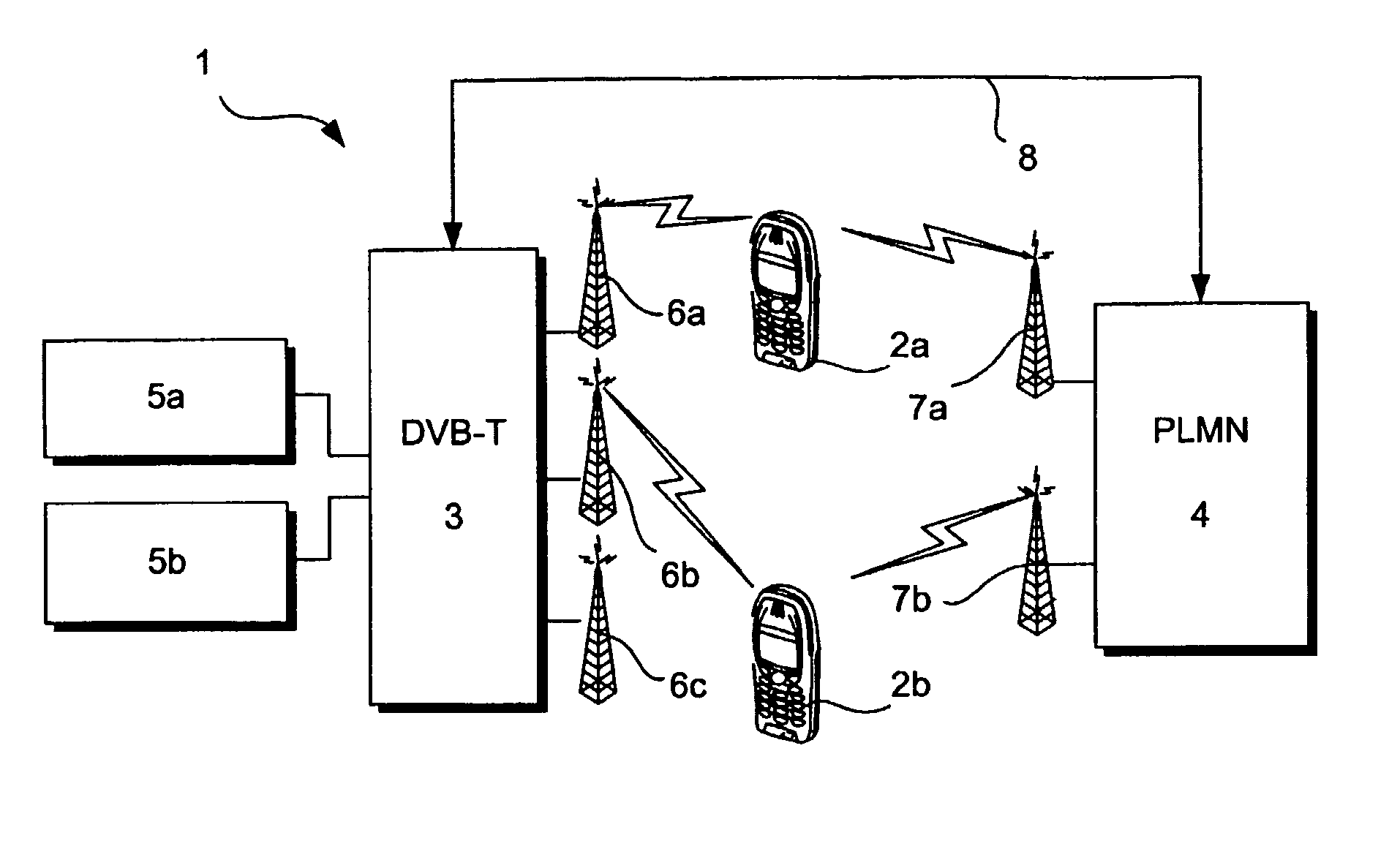
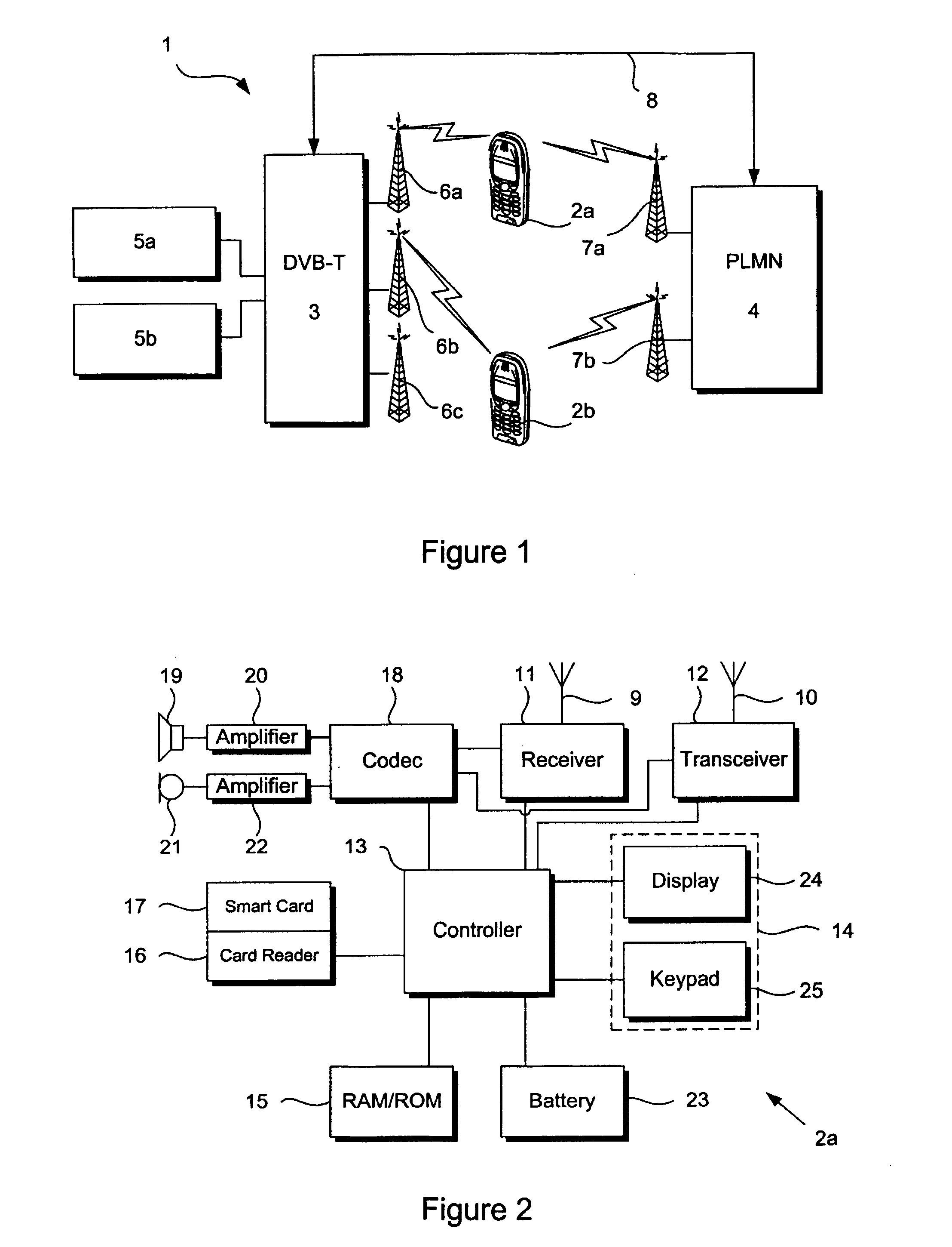
[0028]FIG. 1 illustrates schematically a communication system 1 in which mobile user equipment in the form of mobile terminals, such as telephone handsets 2a, 2b, are configured to receive transmissions from a digital broadcast network 3 which, in this particular example, is a DVB-T network, and to enable communication through a public land mobile network (PLMN) 4. The digital broadcast network 3 transmits content such as audiovisual content, visually displayable data, audio files or data files to the handsets 2a, 2b.

[0029] The content is obtained from data stream servers 5a, 5b in Internet protocol (IP) so that the network can provide an IP Datacast (IPDC) service over the digital broadcast network 3. Two such servers 5a, 5b are shown by way of example although in practice there may be many more. The stream servers 5a, 5b supply content in the form of IP datagrams. The datagrams are embedded into multi-protocol encapsulation (MPE) that are incorporated into MPEG-2 transport stream...


PUM


Abstract

A data receiving device ( 2 a) is arranged to run a media guide application through which a user may access a service provided over broadcast network ( 3 ). Should reception of the service be interrupted, for example, by an incoming telephone call over telecommunications network ( 4 ), the data receiving device ( 2 a) operates in a first resource saving mode where data is received by receiver ( 11 ) but neither processed nor output. The received data may be stored for later output or simply discarded. The service can then be resumed, with minimal delay, by restarting processing and outputting of received data, as it is not necessary to reactivate or resynchronise the receiver ( 11 ). After operating in said first resource saving mode for a predetermined time period, the receiver ( 11 ) may be deactivated in order to further save power. Applications used in receiving, processing and / or outputting the received data, may be closed down following the expiry of one or more further predetermined time periods.

Description

BACKGROUND OF THE INVENTION [0001] The invention relates to a receiving device and method for receiving data that is particularly suitable for reception of digital services over a wireless link. [0002] Proposed services for mobile terminals, such as news, entertainment or business services, require the transmission of content to one or more receiving devices. The content may include audio, video, multimedia, graphic or other data, such as music files or film clips. However, a considerable amount of data is required to provide such services, and the reception and processing of this data may place significant demands on the restricted power and memory capacities of a mobile terminal. [0003] In particular, a mobile terminal may be required to run an unrelated application while receiving a service. For example, where the mobile terminal comprises a telephone handset, it may be required to handle an incoming call while receiving a data stream or, alternatively, a user may wish to access ...

Claims


Application Information

Patent Timeline
IPC IPC(8): H04M1/00H04H20/57H04H40/18H04H60/27H04H60/91H04L29/06H04M1/725H04M1/73H04N7/24H04W88/06
CPCH04H20/426H04H20/57H04H40/18H04H60/27H04H60/91H04L69/18H04M1/72522H04M1/72544H04W52/0274H04W88/06H04H2201/40Y02B60/50
Inventor VERMOLA, LARRISAARIKIVI, TUOMO
Owner NOKIA CORP
Learn More