
Mechanical quantity sensor and method of manufacturing the same

a technology of mechanical quantity sensor and manufacturing method, which is applied in the direction of acceleration measurement using interia force, turn-sensitive devices, instruments, etc., can solve the problems of variation in characteristic among products and differences in capacitance values, and achieve the effect of reducing characteristic variation among products

Inactive Publication Date: 2010-04-08
DAI NIPPON PRINTING CO LTD
View PDF39 Cites 3 Cited by
  • Summary
  • Abstract
  • Description
  • Claims
  • Application Information

AI Technical Summary

Benefits of technology

[0005]Considering the above circumstances, it is an object of the present invention to provide a mechanical quantity sensor realizing a reduction in characteristic variation among products and capable of preventing its driving electrodes which are to be capacitively coupled from coming into contact with each other to be short-circuited, and to provide a method of manufacturing the same.

Problems solved by technology

It has been found out that hillocks, if generated in the driving electrodes, lower dimension precision between the capacitively coupled driving electrodes and thus cause a difference in capacitance value, which may cause variation in characteristic among products.

Method used


Image

  • Mechanical quantity sensor and method of manufacturing the same
  • Mechanical quantity sensor and method of manufacturing the same
  • Mechanical quantity sensor and method of manufacturing the same

Examples


first embodiment

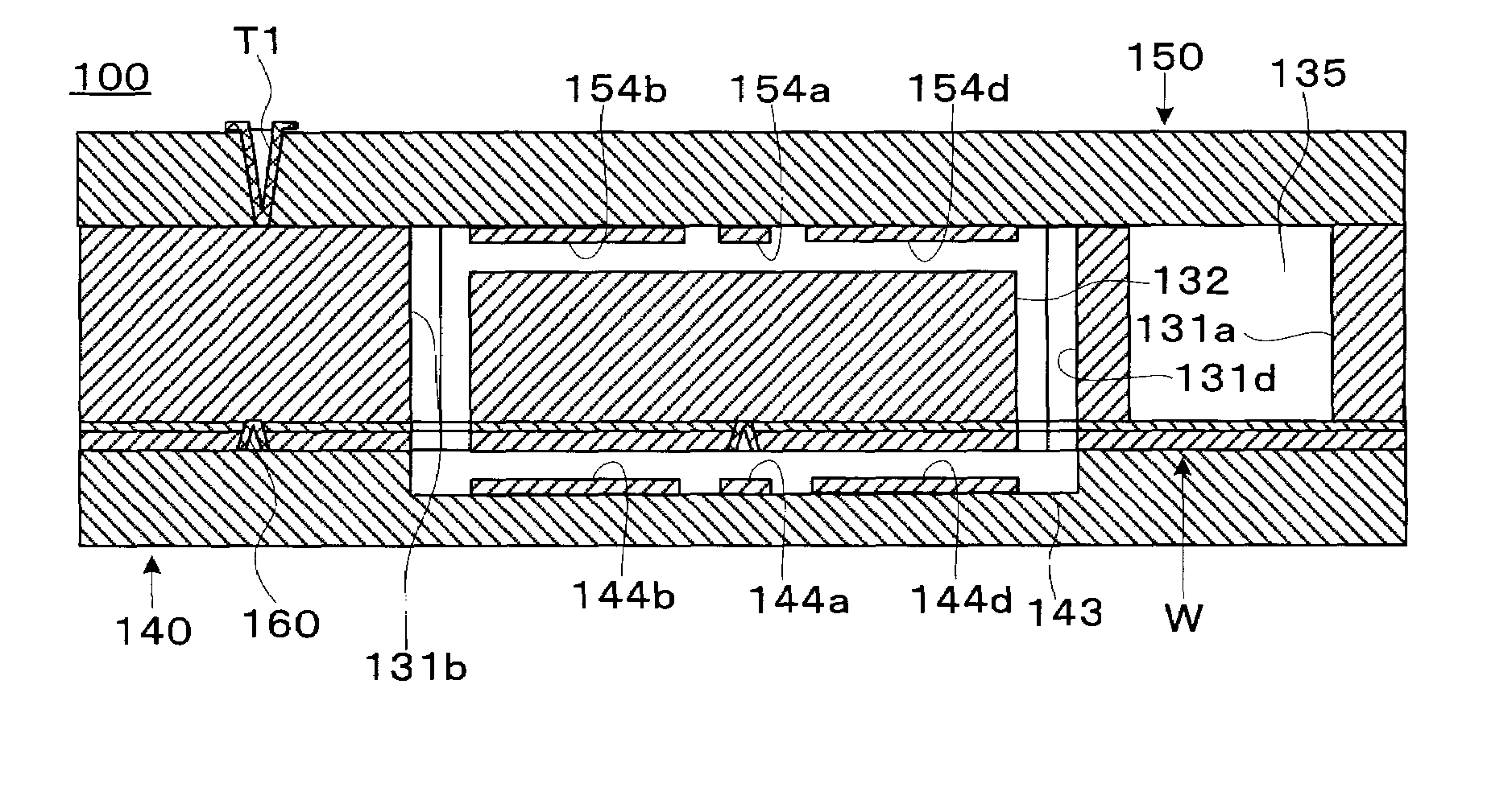
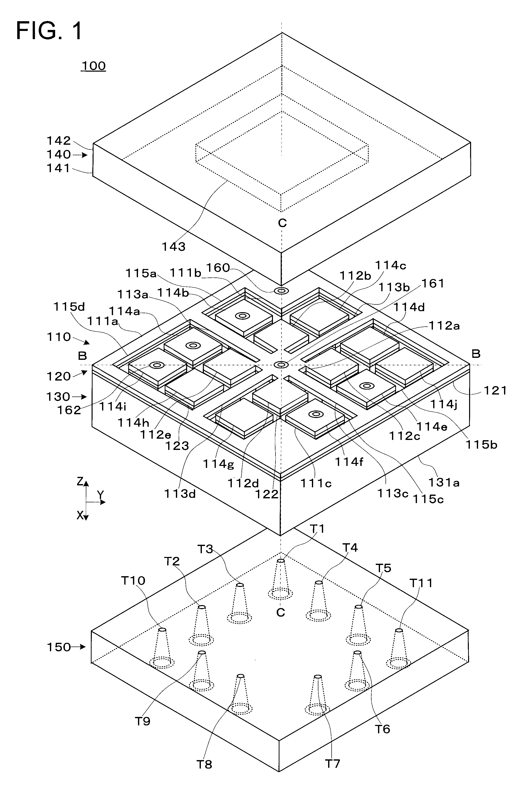
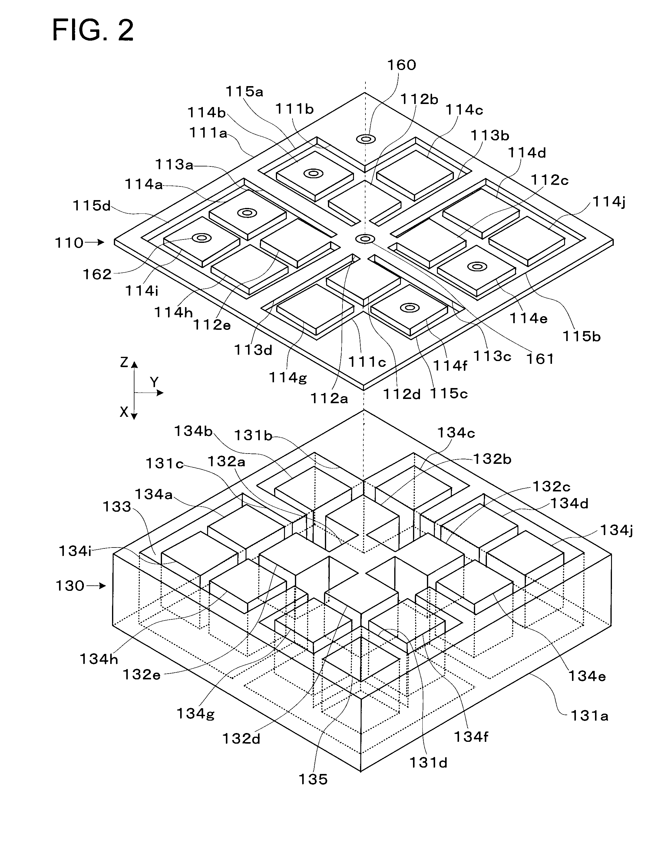
[0032]FIG. 1 is an exploded perspective view showing a state where a mechanical quantity sensor 100 is disassembled. The mechanical quantity sensor 100 has a first structure 110, a joining part 120, and a second structure 130 which are stacked on one another, a first base 140, and a second base 150. FIG. 2 is an exploded perspective view showing a state where part of the mechanical quantity sensor 100 (the first structure 110 and the second structure 130) is further disassembled. FIG. 3, FIG. 4, and FIG. 5 are top views of the first structure 110, the joining part 120, and the second structure 130 respectively. FIG. 6, FIG. 7, and FIG. 8 are a bottom view of the first base 140, a top view of the second base 150, and a bottom view of the second base 150 respectively. FIG. 9 and FIG. 10 are cross-sectional views of the mechanical quantity sensor 100 taken along B-B and C-C in FIG. 1 respectively.

[0033]The mechanical quantity sensor 100 in a stand-alone state or in combination with a c...

example

[0182]Experimental studies were conducted on the material forming the driving electrodes 144a, 154a and so on and the presence / absence of the generation of hillocks.

[0183]Concretely, an Nd-containing Al film was formed on a glass substrate and the presence / absence of the generation of hillocks due to heat treatment was confirmed. As the condition for the heat treatment, the temperature was set to 400° C. and the treatment time was set to one hour. An optical microscope was used to observe the presence / absence of hillocks.

[0184]When a content ratio of Nd is Oat % (pure Al) and 1.3 at %, the generation of hillocks was observed. On the other hand, when the content ratio of Nd is 2.0 at %, the generation of hillocks was not observed. It is inferred from this result that hillocks can be reduced when the content ratio of Nd is about 1.5 at % or higher.

[0185]When the content ratio of Nd was set to 2.0 at % and the treatment time was set to 30 minutes under varied temperatures of 200° C., 3...


PUM


Abstract

A mechanical quantity sensor includes: a first structure having a fixed portion with an opening, a displaceable portion disposed in the opening and displaceable relative to the fixed portion, and a connection portion connecting the fixed portion and the displaceable portion to each other; a second structure having a weight portion joined to the displaceable portion and a pedestal joined to the fixed portion, the second structure being stacked on the first structure; a first base having a first driving electrode which is disposed on a surface facing the displaceable portion and is made of a conductive material containing Al and Nd, the first base being stacked on the first structure while being connected to the fixed portion; and a second base having a second driving electrode which is disposed on a surface facing the weight portion and is made of the conductive material, the second base being stacked on the second structure while being connected to the pedestal.

Description

TECHNICAL FIELD[0001]The present invention relates to a mechanical quantity sensor detecting a mechanical quantity, and to a method of manufacturing the same.BACKGROUND ART[0002]There has been disclosed a technique of an angular velocity sensor detecting an angular velocity, in which a transducer structure made of a semiconductor is joined to a glass substrate (see patent reference 1).[0003]Patent reference 1: JP-A 2002-350138 (KOKAI)DISCLOSURE OF THE INVENTION[0004]However, if driving electrodes which apply stack-direction vibration to a weight portion are made of Al, hillocks (for example, semispherical protuberances) are sometimes generated in the driving electrodes when the transducer structure and the glass substrate are anodically bonded. It has been found out that hillocks, if generated in the driving electrodes, lower dimension precision between the capacitively coupled driving electrodes and thus cause a difference in capacitance value, which may cause variation in characte...

Claims


Application Information

Patent Timeline
Patent Type & Authority Applications(United States)
IPC IPC(8): G01C19/56H01L21/30G01C19/5733G01C19/5769G01P15/18
CPCG01C19/5733G01C19/5769G01C25/00G01P15/0802G01P15/097G01P15/125G01P15/18G01P2015/0842
Inventor MORII, AKIO
Owner DAI NIPPON PRINTING CO LTD
Learn More