
Image log slope (ILS) optimization

a technology of image logs and optimization, applied in the field of lithographic apparatuses and processes, can solve problems such as the difficulty of reproducing patterns on the substrate, and achieve the effect of reducing the stochastic variation and reducing the characteristi

Active Publication Date: 2018-01-11
ASML NETHERLANDS BV
View PDF2 Cites 10 Cited by
  • Summary
  • Abstract
  • Description
  • Claims
  • Application Information

AI Technical Summary

Benefits of technology

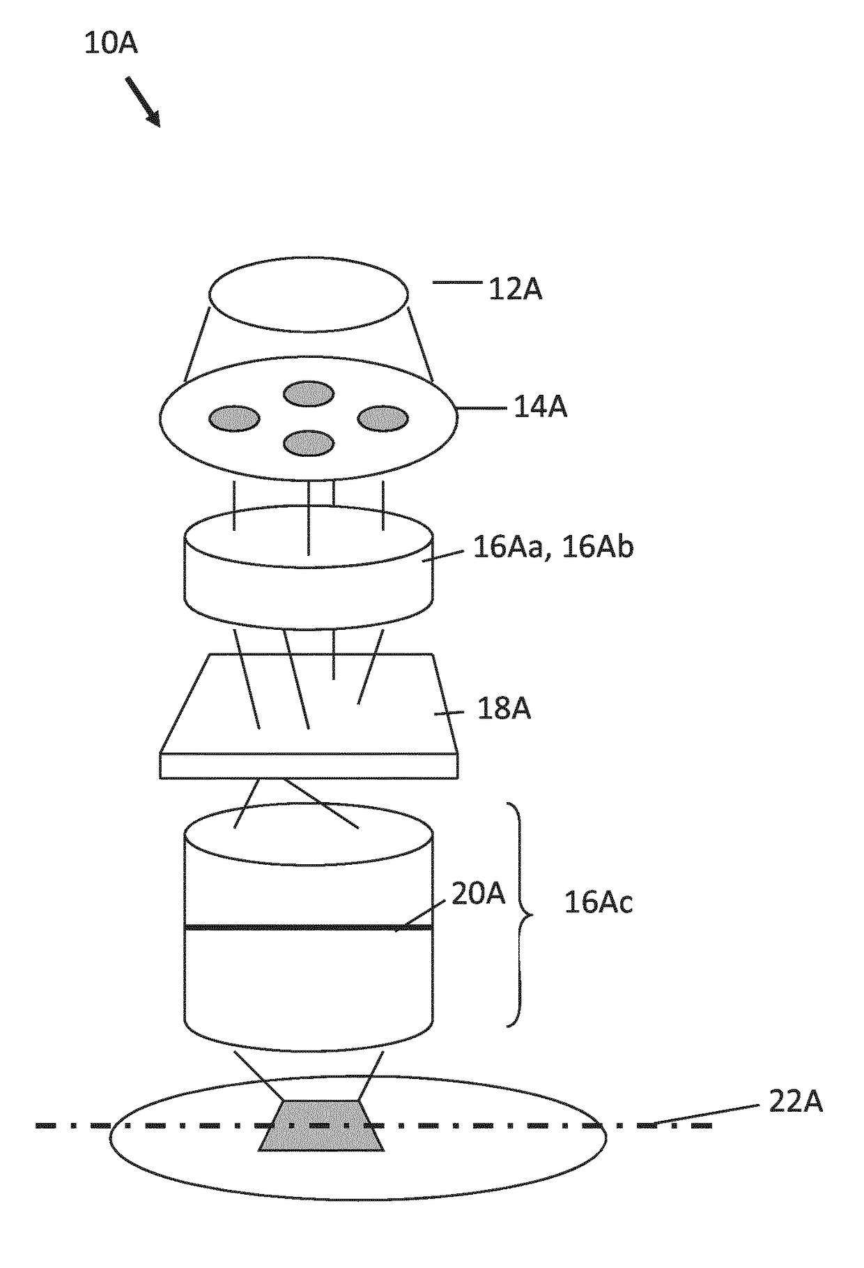
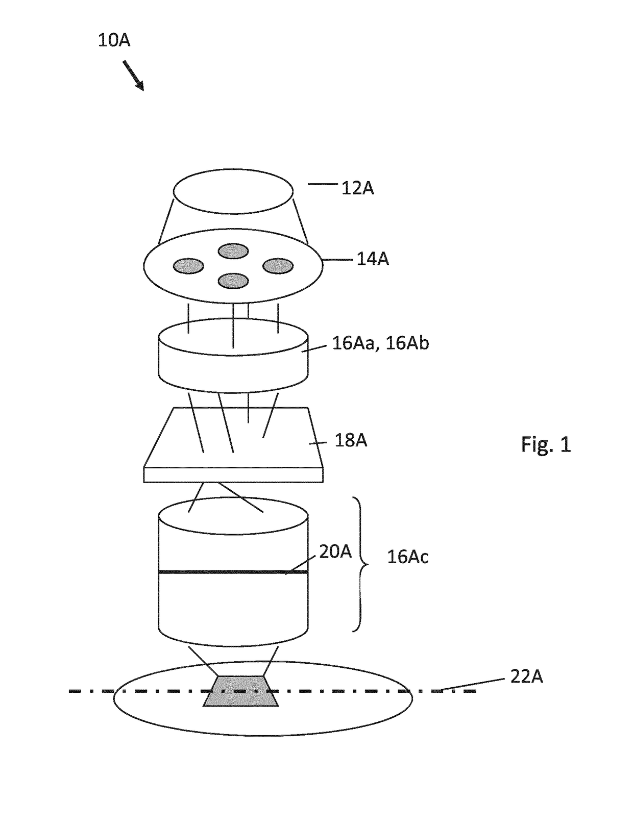
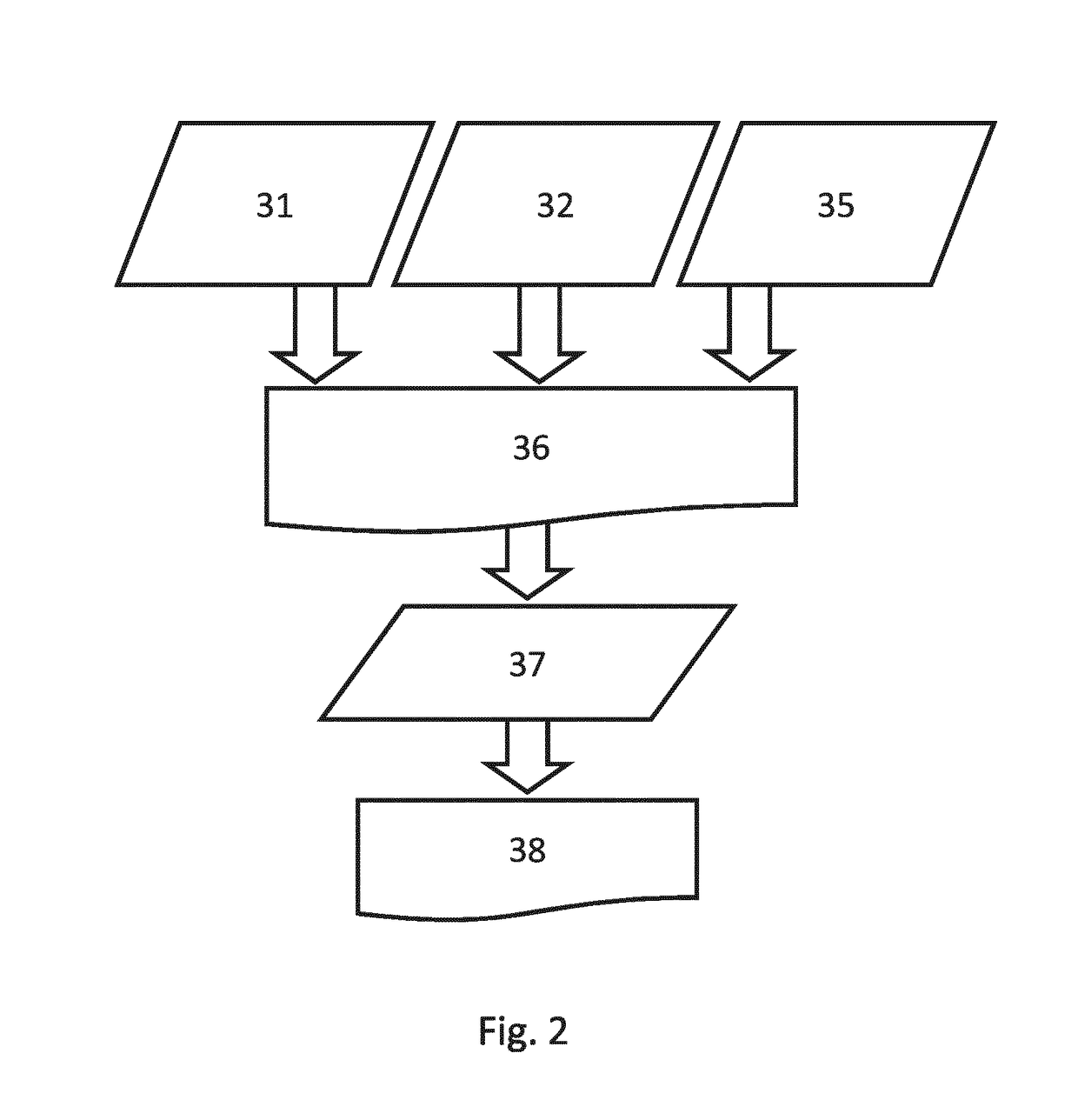
This patent describes a method for reducing stochastic variations in the characteristics of an aerial image or resist image. The method involves identifying a hot spot in a design layout and optimizing one or more portions of the layout to reduce the stochastic variation. Various algorithms such as Gauss-Newton, Levenberg-Marquardt, Broyden-Fletcher-Goldfarb-Shanno, gradient descent, simulated annealing, interior point, and genetic algorithm can be used to minimize or maximize a cost function to achieve the desired result.

Problems solved by technology

In general, the smaller k1 the more difficult it becomes to reproduce a pattern on the substrate that resembles the shape and dimensions planned by a circuit designer in order to achieve particular electrical functionality and performance.

Method used


Image

  • Image log slope (ILS) optimization
  • Image log slope (ILS) optimization
  • Image log slope (ILS) optimization

Examples


Embodiment Construction

[0063]Although specific reference may be made in this text to the manufacture of

[0064]ICs, it should be explicitly understood that the description herein has many other possible applications. For example, it may be employed in the manufacture of integrated optical systems, guidance and detection patterns for magnetic domain memories, liquid-crystal display panels, thin-film magnetic heads, etc. The skilled artisan will appreciate that, in the context of such alternative applications, any use of the terms “reticle”, “wafer” or “die” in this text should be considered as interchangeable with the more general terms “mask”, “substrate” and “target portion”, respectively.

[0065]In the present document, the terms “radiation” and “beam” are used to encompass all types of electromagnetic radiation, including ultraviolet radiation (e.g. with a wavelength of 365, 248, 193, 157 or 126 nm) and EUV (extreme ultra-violet radiation, e.g. having a wavelength in the range 5-20 nm).

[0066]The term “opti...


PUM

PropertyMeasurementUnit
wavelengthaaaaaaaaaa

Abstract

A method to improve a lithographic process of imaging a portion of a design layout onto a substrate using a lithographic projection apparatus, the method including: computing a multi-variable cost function, the multi-variable cost function being a function of a stochastic variation of a characteristic of an aerial image or a resist image, or a function of a variable that is a function of the stochastic variation or that affects the stochastic variation, the stochastic variation being a function of a plurality of design variables that represent characteristics of the lithographic process; and reconfiguring one or more of the characteristics of the lithographic process by adjusting one or more of the design variables until a certain termination condition is satisfied.

Description

CROSS-REFERENCE TO RELATED APPLICATIONS[0001]This application claims the benefit of U.S. provisional application 62 / 116,048, which was filed on Feb. 13, 2015 and which is incorporated herein in its entirety by reference.TECHNICAL FIELD[0002]The description herein relates to lithographic apparatuses and processes, and more particularly to a method or apparatus to optimize an illumination and / or patterning device / design layout for use in a lithographic apparatus or process.BACKGROUND[0003]A lithographic projection apparatus can be used, for example, in the manufacture of integrated circuits (ICs). In such a case, a patterning device (e.g., a mask) may contain or provide a circuit pattern corresponding to an individual layer of the IC (“design layout”), and this circuit pattern can be transferred onto a target portion (e.g. comprising one or more dies) on a substrate (e.g., silicon wafer) that has been coated with a layer of radiation-sensitive material (“resist”), by methods such as i...

Claims


Application Information

Patent Timeline
Patent Type & Authority Applications(United States)
IPC IPC(8): G03F7/20
CPCG03F7/705G03F7/70441G03F7/70625G03F7/70433G03F7/70508G03F7/70666G03F7/70675
Inventor HSU, DUAN-FU STEPHEN
Owner ASML NETHERLANDS BV
Learn More