Substrate processing apparatus

a processing apparatus and substrate technology, applied in the direction of liquid surface applicators, coatings, chemical vapor deposition coatings, etc., to achieve the effect of improving and uniformity of film thickness

Inactive Publication Date: 2010-04-08
KOKUSA ELECTRIC CO LTD
View PDF16 Cites 37 Cited by
  • Summary
  • Abstract
  • Description
  • Claims
  • Application Information

AI Technical Summary

Benefits of technology

[0147]According to this embodiment, one or a plurality of advantages are exhibited as shown below.
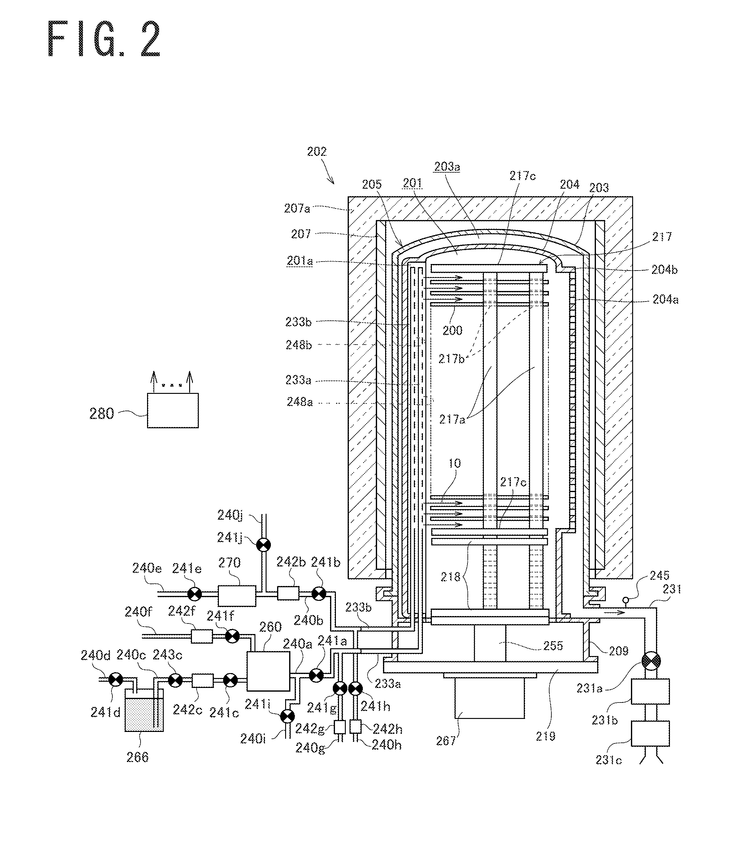
[0148](a) The side wall of the inner tube 204 of this embodiment is constituted, so that the distance L2 between the outer edge of the wafer 200 stored in the inner tube 204 and the gas exhaust holes 204a is set to be longer than the distance L1 between the outer edge of the wafer 200 stored in the inner tube 204 and the vaporized gas ejection holes 248a. Also, similarly the side wall of the inner tube 204 is constituted, so that the distance L2 between the outer edge of the wafer 200 store in the inner tube 204 and the gas exhaust holes 204a is set to be longer than the distance L1 between the outer edge of the wafer 200 stored in the inner tube 204 and the reactive gas ejection holes 248b. Thus, by securing the distance between the outer edge of the wafer 200 and the gas exhaust holes 204a to be longer, the area, where the velocity of the gas flow 10 is increased, can be distanced from the wafer 200 and the velocity of the gas flow 10 on the wafer 200 can be uniformized. Then, the flow rate of the gas supplied to the wafer 200 can be uniformized and the uniformity of the film thickness can be improved.
[0149](b) Further, the side wall of the inner tube 204 of this embodiment is constituted, so that the distance L2 between the outer edge of the wafer 200 stored in the inner tube 204 and the gas exhaust holes 204a is set to be longer than the distance L3 between the side wall (“second part”) of the inner tube 204, with no gas exhaust holes 204a opened, and the outer edge of the wafer 200 stored in the inner tube 204. Thus, by securing the distance between the outer edge of the wafer 200 and the gas exhaust holes 204a to be longer, the area, where the velocity of the gas flow 10 is increased, can be distanced from the wafer 200, and the velocity of the gas flow 10 on the wafer 200 can be uniformized. Then, the flow rate of the gas supplied to the wafer 200 can be uniformized and the uniformity of the film thickness can be improved.
[0150](c) Moreover, the side wall

Problems solved by technology

However, when a conventional substrate processing apparatus is used, a film thickness of the formed thin film becom

Method used


Image

  • Substrate processing apparatus
  • Substrate processing apparatus
  • Substrate processing apparatus

Examples


examples

[0153]Examples of the present invention will be described hereinafter, compared with comparative examples.

[0154]FIG. 10 is a graph chart showing a measurement result of a film thickness distribution of a thin film formed on the wafer 200, wherein symbol ◯ indicates an example 1, symbol ▪ indicates a comparative example 1, respectively. In FIG. 10, the distance from the center of the wafer 200 is taken on the horizontal axis, and the film thickness of the ZrO2 film formed on the wafer 200 is taken on the vertical axis. FIG. 11 is a schematic view showing the film thickness distribution of the thin film formed on the wafer by a contour line, wherein FIG. 11A shows example 1 of the present invention, FIG. 11B shows example 2 of the present invention, FIG. 11C shows comparative example 1, and FIG. 11D shows comparative example 2, respectively.

[0155]In the example 1 shown by symbol ◯ and FIG. 11A, the distance L2 between the outer edge of the wafer 200 stored in the inner tube 204 and th...


PUM

PropertyMeasurementUnit
Pressureaaaaaaaaaa
Pressureaaaaaaaaaa
Pressureaaaaaaaaaa

Abstract

There are provided an inner tube in which a substrate is stored; an outer tube surrounding the inner tube; a gas nozzle disposed in the inner tube; a gas ejection hole opened on the gas nozzle; a gas supply unit supplying gas into the inner tube through the gas nozzle; a gas exhausts hole opened on the side wall of the inner tube; and an exhaust unit exhausting a space between the outer tube and the inner tube and generating a gas flow in the inner tube toward the gas exhaust hole from the gas ejection hole, wherein the side wall of the inner tube is constituted, so that a distance between an outer edge of the substrate and the gas exhaust hole is set to be longer than a distance between the outer edge of the substrate and the gas ejection hole.

Description

BACKGROUND[0001]1. Technical Field[0002]The present invention relates to a substrate processing apparatus for processing a substrate.[0003]2. Description of Related Art[0004]Conventionally, a substrate processing step for forming a thin film on a substrate has been executed, as one step of manufacturing steps of a semiconductor device such as DRAM. The substrate processing step has been executed by a substrate processing apparatus including: an inner tube in which a substrate is stored; an outer tube surrounding the inner tube; a gas supply unit supplying gas into the inner tube; and an exhaust unit generating a gas flow in the inner tube by exhausting a space between the outer tube and the inner tube. Then, the thin film has been formed on the substrate, by supplying the gas to the substrate from a horizontal direction.[0005]However, when a conventional substrate processing apparatus is used, a film thickness of the formed thin film becomes thick at an outer edge part of the substr...

Claims


Application Information

Patent Timeline
IPC IPC(8): C23C16/52C23C16/00
CPCC23C16/405C23C16/45546H01L21/67109H01L21/3141H01L21/31641C23C16/45578H01L21/0228H01L21/02189C23C16/52H01L21/0262
Inventor KOGURA, SHINTAROTAKEBAYASHI, YUJIASHITANI, ATSUHIKOOKADA, SATOSHI
Owner KOKUSA ELECTRIC CO LTD
Why Eureka
Try Eureka