
Solar cell module

a solar cell module and module technology, applied in the field of electronic modules, can solve the problems of deteriorating manufacturing efficiency, increasing manufacturing cost, and deteriorating reliability of solar cell modules, so as to improve product reliability, improve manufacturing efficiency, and reduce cost

Inactive Publication Date: 2010-04-08
PEGATRON
View PDF3 Cites 20 Cited by
  • Summary
  • Abstract
  • Description
  • Claims
  • Application Information

AI Technical Summary

Benefits of technology

[0009]This invention provides a solar cell module capable of improving manufacturing efficiency, reducing cost, and improving product reliability to improve the prior art.
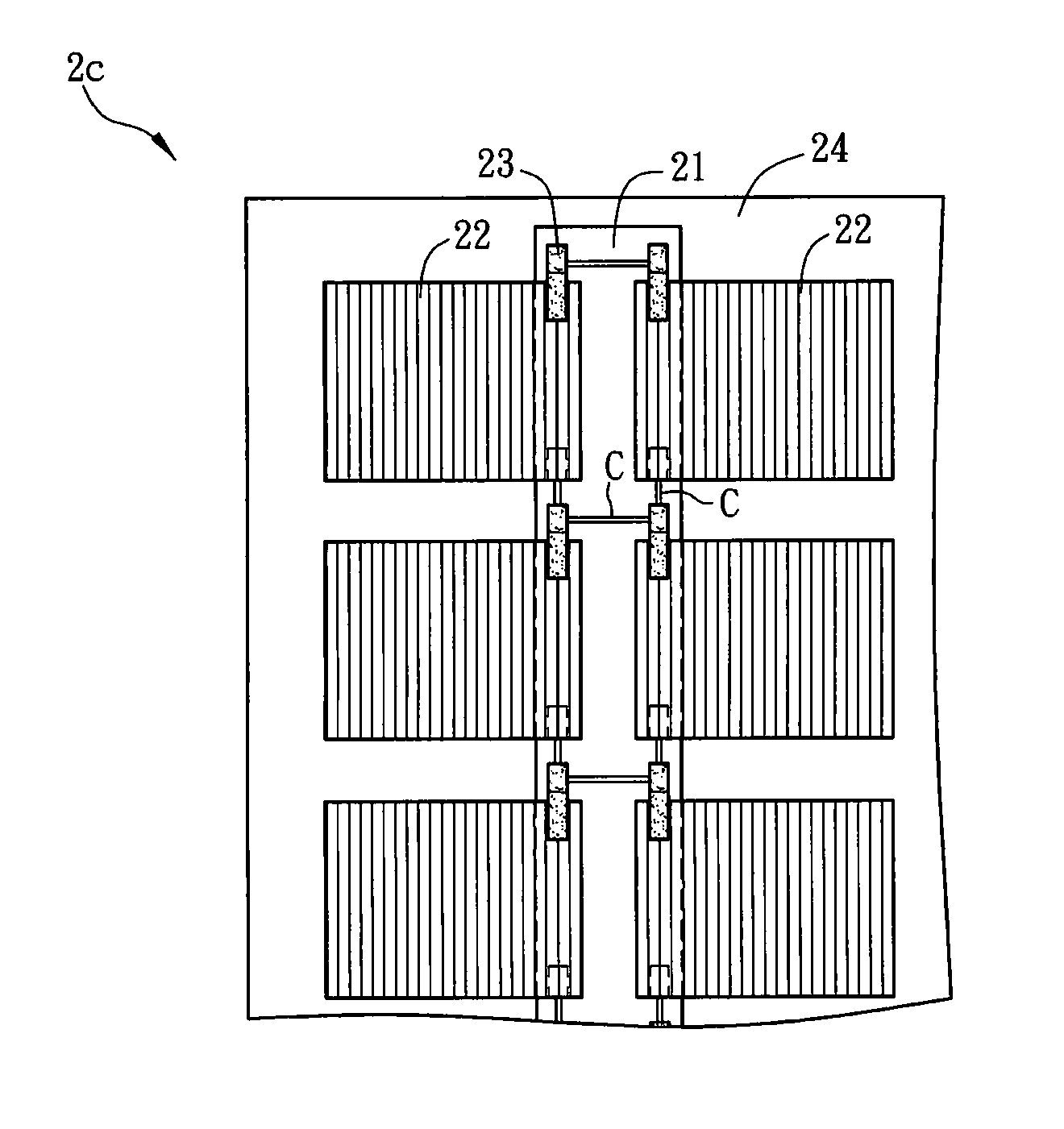
[0014]According to the solar cell module in the invention, a circuit board is used to be connected with the solar cell elements. Therefore, the solar cell elements can be connected in series or in parallel via the circuit disposed at the circuit board, and the solar cell elements can be directly connected with the circuit board via surface-mount technology (SMT). Thereby, the solar cell module can be manufactured via an automatic manufacturing process to improve the manufacturing efficiency and to avoid defects caused by manual operation, further to improve reliability of the solar cell module. In addition, the solar cell module in the invention can further use a conductor, two circuit boards, or a flexible circuit board and so on to allow the electrodes located at different surfaces of the solar cell elements to be capable of being connected with the circuit board.
[0015]In addition, the solar cell element of the solar cell module is partly protrudent from the circuit board. Therefore, the solar cell element is not fully disposed on the circuit board. In other words, the size of the circuit board in the invention does not need to be too large, thereby avoiding increasing cost. Thus the circuit board can be prevented from covering the solar cell elements to reduce a light-receiving area of the solar cell elements.

Problems solved by technology

With exhaustion of consuming energy and improvement of global environmental consciousness, how to effectively use different energy has become one important issue at present.
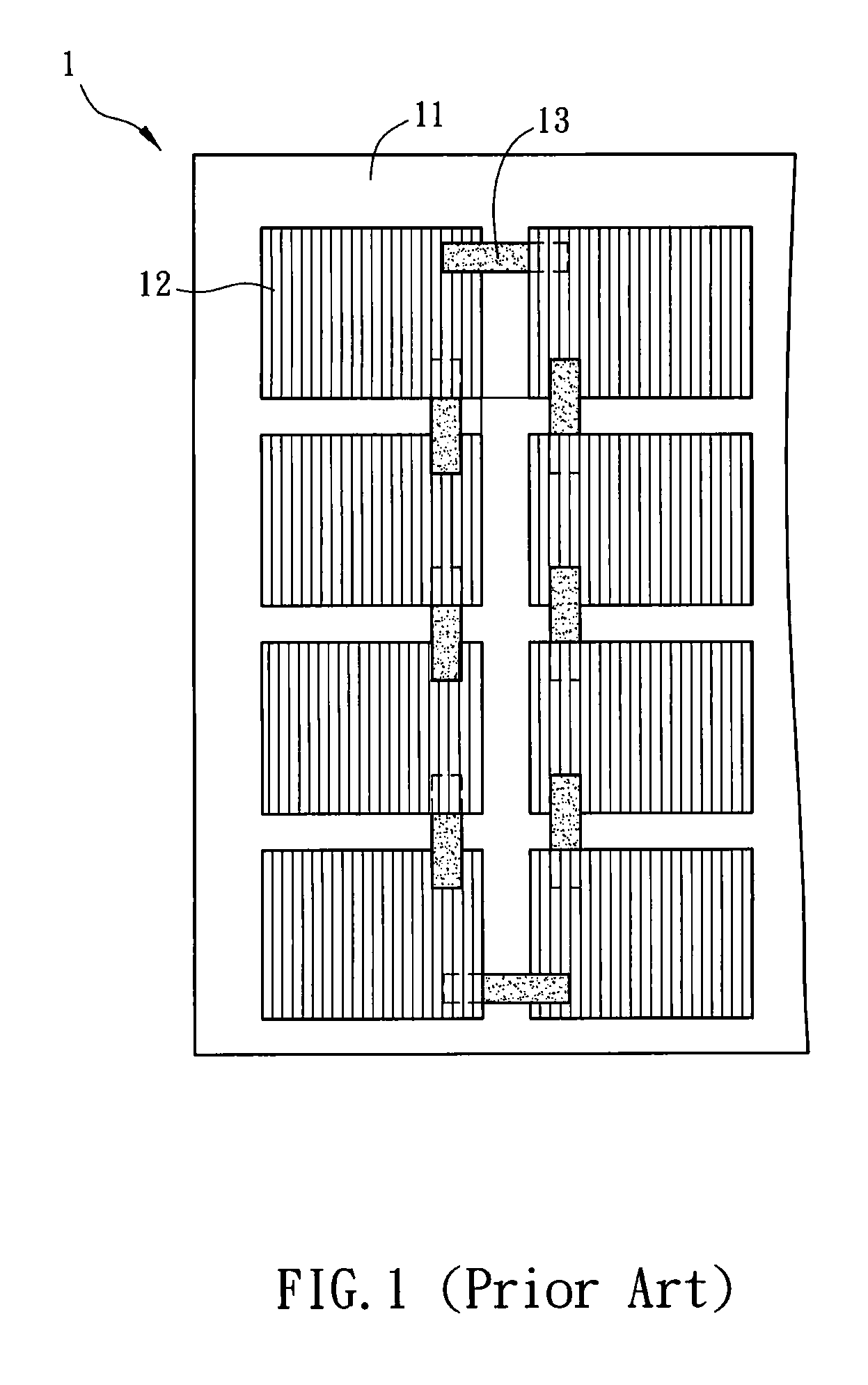
Thus the manufacturing efficiency of the solar cell module 1 is deteriorated and the manufacturing cost increases.
In addition, manual carelessness during the manual soldering operation may cause defects of the solar cell module 1, further to deteriorate reliability of the solar cell module 1.

Method used


Image

  • Solar cell module
  • Solar cell module
  • Solar cell module

Examples


Embodiment Construction

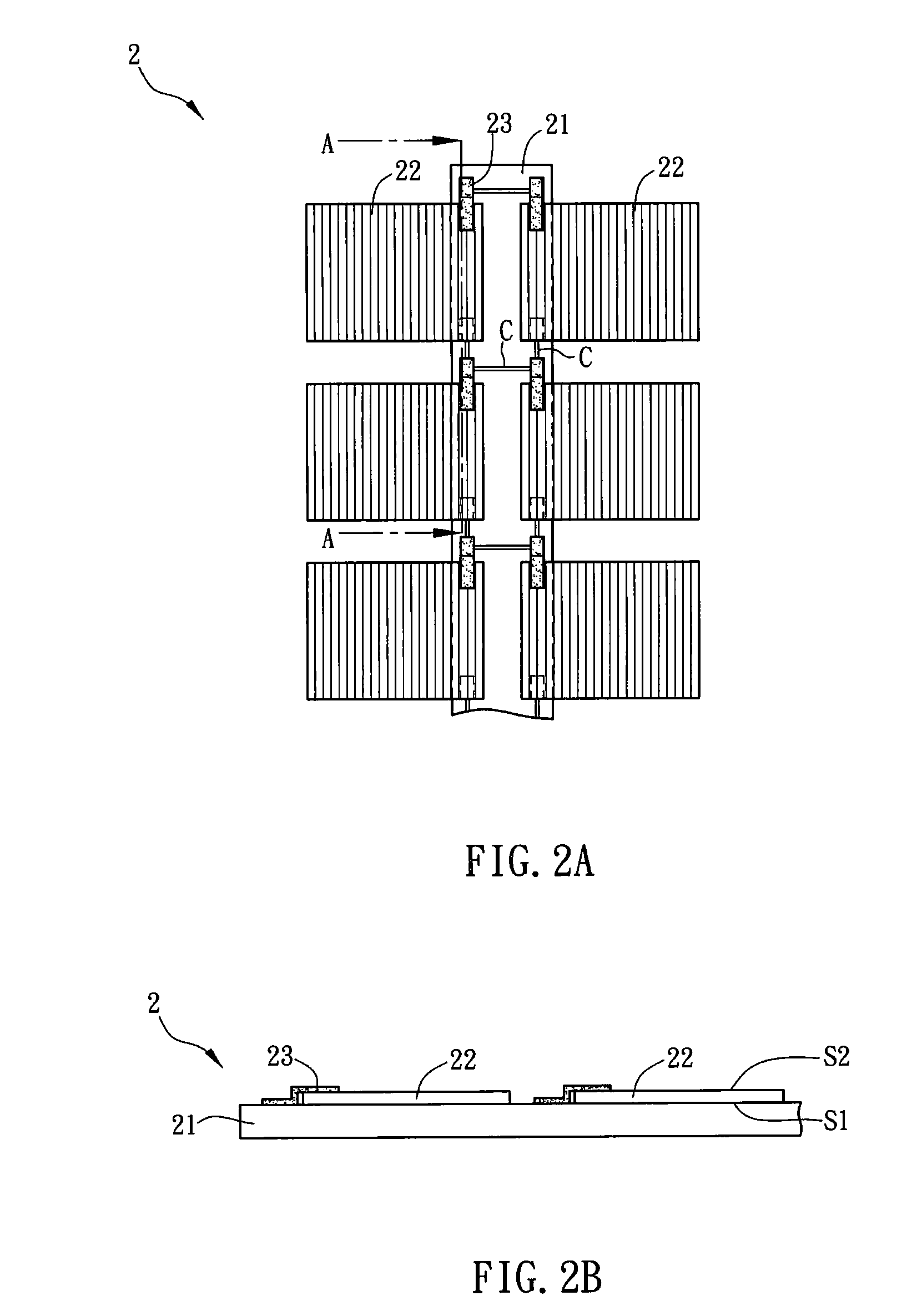
[0021]FIG. 2A is a schematic diagram showing a solar cell module 2 according to one preferred embodiment of the invention. FIG. 2B is a sectional schematic diagram showing the solar cell module 2 along a line A-A in FIG. 2A. The solar cell module 2 includes a circuit board 21 and a plurality of solar cell elements 22.

[0022]The circuit board 21 may be made of glass, sapphire, quartz, or plastic.

[0023]The solar cell element 22 may be a photovoltaic cell which may be a thin film solar cell element, a mono-crystalline silicon solar cell element, a poly-crystalline silicon solar cell element, or an organic solar cell element. The organic solar cell element may be a dye-sensitized solar cell element.

[0024]The solar cell element 22 is connected with the circuit board 21. The solar cell element 22 is partly fastened to the circuit board 21 and is partly protrudent from the circuit board 21. In other words, the solar cell element 22 is not fully disposed on the circuit board 21, and only par...


PUM


Abstract

A solar cell module includes a circuit board and a plurality of solar cell elements. Each of the solar cell elements is partly fastened to the circuit board and is partly protrudent from the circuit board.

Description

CROSS REFERENCE TO RELATED APPLICATIONS[0001]This Non-provisional application claims priority under 35 U.S.C. §119(a) on Patent Application No(s). 097138424 filed in Taiwan, Republic of China on Oct. 6, 2008, the entire contents of which are hereby incorporated by reference.BACKGROUND OF THE INVENTION[0002]1. Field of Invention[0003]The invention relates to an electronic module and, more particularly, to a solar cell module.[0004]2. Related Art[0005]With exhaustion of consuming energy and improvement of global environmental consciousness, how to effectively use different energy has become one important issue at present. Since solar energy is one kind of common energy in our life, the solar cell technique has become one important developing direction.[0006]FIG. 1 is a schematic diagram showing a conventional solar cell module 1. In FIG. 1, the conventional solar cell module 1 includes a supporting element 11 and a plurality of solar cell elements 12. The supporting element 11 support...

Claims


Application Information

Patent Timeline
Patent Type & Authority Applications(United States)
IPC IPC(8): H01L31/042
CPCH01L31/0504Y02E10/50H05K1/189H01L31/0512
Inventor CHEN, CHIEN-AN
Owner PEGATRON
Learn More