Scaffolding systems

a scaffolding and system technology, applied in the direction of building scaffolds, rod connections, furniture joining, etc., can solve the problems of large unitary planks that are difficult to raise and lower to and from elevated locations, large planks that are difficult to transport, and are at risk of falling from the scaffolding, so as to eliminate the tripping hazard, save labor and transportation costs, and strengthen the scaffolding platform

Inactive Publication Date: 2010-04-08
CLEVELAND LEWIS ROY
View PDF13 Cites 6 Cited by
  • Summary
  • Abstract
  • Description
  • Claims
  • Application Information

AI Technical Summary

Benefits of technology

[0051]Furthermore, the provision of complimentary male and female connectors in the side walls of support components and also preferably when used in conjunction with support clamps can allow a relatively strong scaffolding platform to be formed.
[0052]The present invention may be employed to form a unitary scaffolding platform with dimensions directly dictated by the current requirements of the user. Each unitary platform can eliminate the tripping hazard caused by the overlapped plank ends employed in prior art systems. Furthermore the unitary nature of such a platform also eliminates the independent flexing of planks lying side by side as can be found in prior art systems.
[0053]The joining component discussed also allows for the connection of the ends of support components together, without these component ends needing to be sited above a horizontal bar of the scaffolding framework. These joining components may be utilised anywhere required to provide a platform dimensioned to suit the requirements of a user.
[0054]The flexible nature of the present invention also allows the single system provided to service a wider number and range of individual applications. Provided enough components are available the present invention may perform in large or small scale roles, eliminating the need for scaffolding users to hold stock of various lengths of planks for different types of jobs. Additional savings in labour and transportation costs are also available through use of the present invention which allows a scaffolding system to be erected, disassembled and transported rapidly by a minimum number of workers.
[0055]Further, the present invention offers a scaffolding system which is considerably safer than those known in the prior art. Particularly, this is due to the fact that support components connecting in an end on matter via joining components removes the need for butt-joining or planks to overlap, substantially above a support rail as presently needed. Therefore, the present invention is not prone to tipping of planks and removes a significant risk to the safety of users.

Problems solved by technology

Due to their bulk and weight these large planks can be difficult and dangerous to raise and lower to and from elevated locations, particularly in bad weather conditions.
Furthermore, such large unitary planks can be difficult to transport without an appropriate roof rack, trailer or truck being available.
However, lapped sets of plank ends cause a safety hazard which may be tripped over by workers, putting them at risk of falling from the scaffolding.
If this does not occur, then the planks have a higher chance of being tipped over when in use.
However, this arrangement of sets of planks is not optimum as there is no interlinking or connection provided between the planks, resulting in each flexing and moving independently when loaded.
This problem can again cause a safety issue, particularly when a worker is carrying a load and may not have a clear view of the path they are following.

Method used


Image

  • Scaffolding systems
  • Scaffolding systems
  • Scaffolding systems

Examples


Embodiment Construction

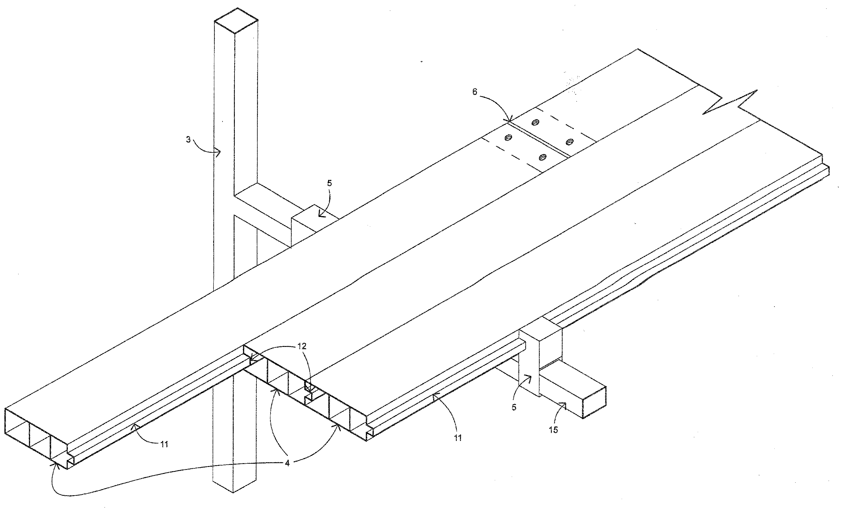
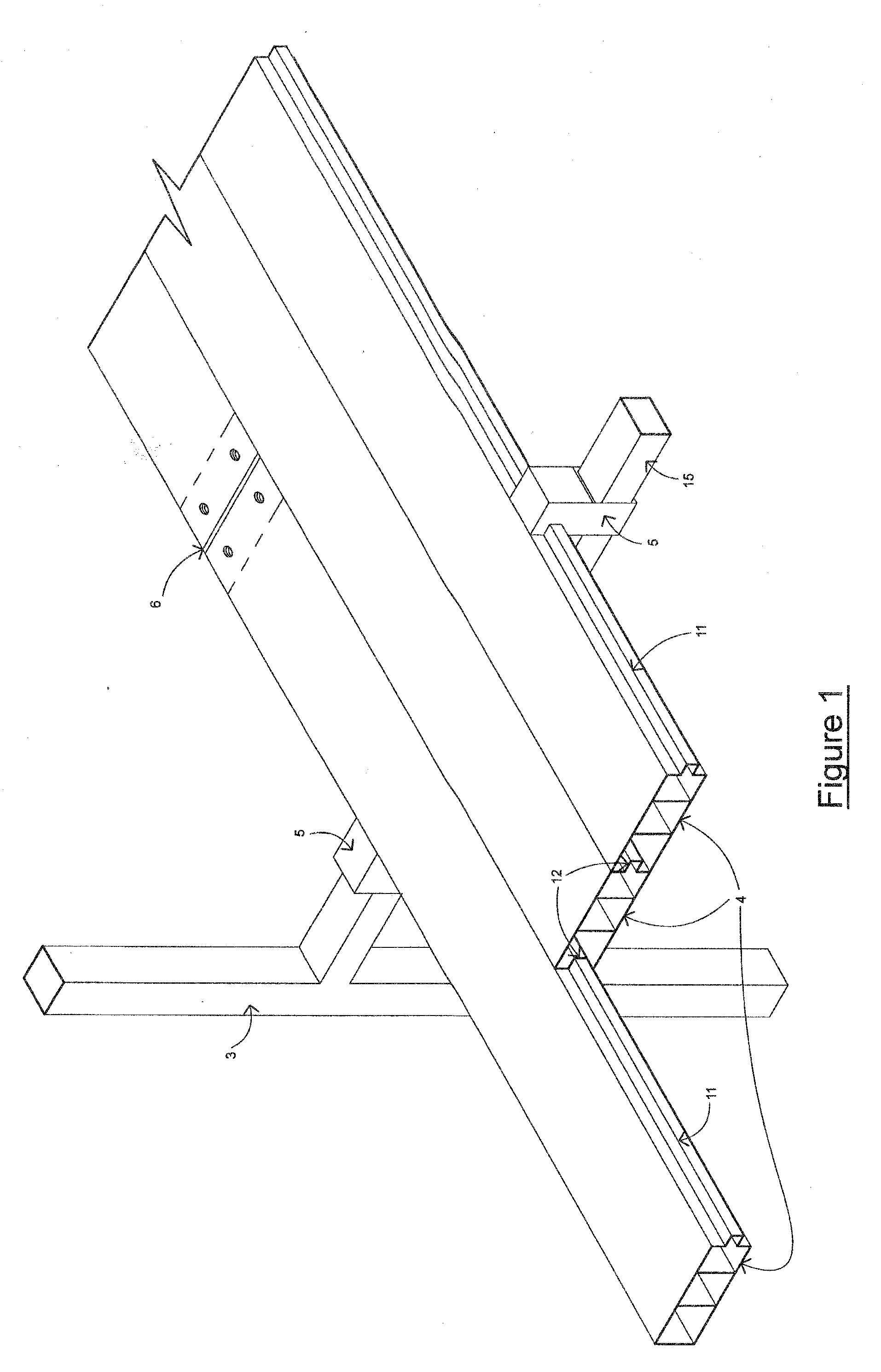
[0065]FIG. 1 shows an improved scaffolding system (1) which is formed by a conglomerate scaffolding platform (2) supported by a framework (3) (not fully shown).

[0066]The conglomerate scaffolding platform (2) is formed by a plurality of support components (4) which are located together. The side walls of the support components (4) are located together through the use of at least one support clamp (5). In the embodiment shown with respect to FIG. 1 a set of three support components are aligned together with their side walls in contact with one another to set the final overall width of the platform formed.

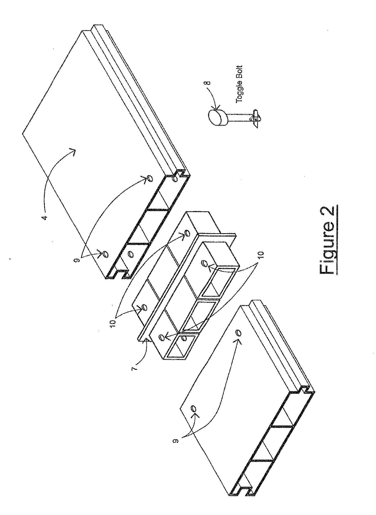
[0067]A number of support components can also be joined end to end through the use of joining components (6), as illustrated with respect to FIG. 2.

[0068]FIG. 2 shows the provision of a joining component (6) formed from a main body (7) and a number of linkage elements (8). The main body defines two opposed projecting portions which have the complimentary form or shape to apertures for...


PUM

PropertyMeasurementUnit
lengthsaaaaaaaaaa
lengthaaaaaaaaaa
cross sectional areaaaaaaaaaaa

Abstract

The present invention relates to a support component configured to provide a portion of a scaffolding platform, the support component including, a main body, and at least one male connector projecting from the main body, and at least one female connector defined by a cavity formed in the main body, wherein the male and female connectors co-operate with complementary connectors of further support elements to form a scaffolding platform.

Description

STATEMENT OF CORRESPONDING APPLICATIONS[0001]This application is based on the Provisional specification filed in relation to New Zealand Patent Application Number 552072, the entire contents of which are incorporated herein by reference.TECHNICAL FIELD[0002]This invention relates to improvements in or relating to scaffolding systems. In particular the present invention may be employed to provide an improved scaffolding platform which can be readily assembled when needed, and disassembled for transportation.BACKGROUND ART[0003]Scaffolding systems can be employed to provide a stable and strong support surface for people working in elevated environments. Well known scaffolding systems generally consist of some form of collapsible framework which supports the ends of one or more scaffolding planks so positioned to allow a person to work in a standing or sitting position.[0004]It is important that the scaffolding employed is both stable and strong enough to support the weight of any pers...

Claims


Application Information

Patent Timeline
Patent Type & Authority Applications(United States)
IPC IPC(8): E04G5/08E04G7/20B23P11/00
CPCE04G1/15Y10T403/55Y10T29/49826
Inventor CLEVELAND, LEWIS ROY
Owner CLEVELAND LEWIS ROY
Why Eureka
Try Eureka