Speed increaser

a speed increaser and gear box technology, applied in the direction of machines/engines, electric generator control, gearboxes for wind turbine applications, etc., can solve the problems of complex multi-stage gear arrangement, difficult service, bulky and heavy gearboxes, etc., to reduce the complexity, size and weight of gearboxes, and increase the speed of input shafts.

Inactive Publication Date: 2010-04-08
ADI WIND
View PDF6 Cites 29 Cited by
  • Summary
  • Abstract
  • Description
  • Claims
  • Application Information

AI Technical Summary

Benefits of technology

[0004]It has thus been desired to provide a way or means of reducing the complexity, size and weight of a gear box for substantially increasing the speed of an input shaft and particularly for wind turbine generator applications.

Problems solved by technology

Presently, gear boxes for wind turbine applications are complex multi-stage gearing arrangements which are not only bulky and heavy but quite difficult to service when installed on the wind turbine tower.

Method used


Image

  • Speed increaser
  • Speed increaser
  • Speed increaser

Examples


Embodiment Construction

[0035]A more complete understanding of the components, processes and apparatuses disclosed herein can be obtained by reference to the accompanying drawings. These figures are merely schematic representations based on convenience and the ease of demonstrating the present disclosure, and are, therefore, not intended to indicate relative size and dimensions of the devices or components thereof and / or to define or limit the scope of the exemplary embodiments.

[0036]Although specific terms are used in the following description for the sake of clarity, these terms are intended to refer only to the particular structure of the embodiments selected for illustration in the drawings, and are not intended to define or limit the scope of the disclosure. In the drawings and the following description below, it is to be understood that like numeric designations refer to components of like function.

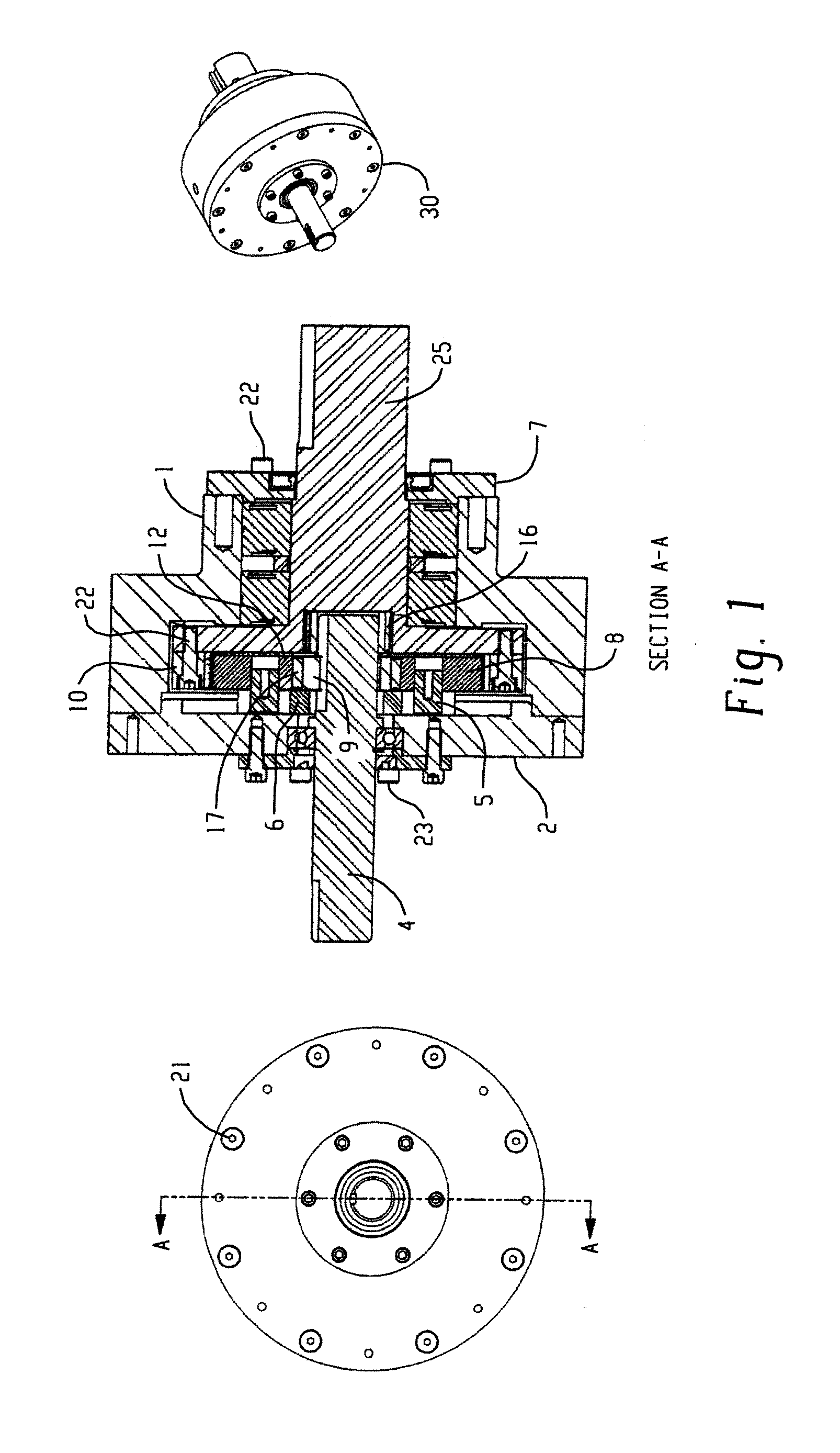
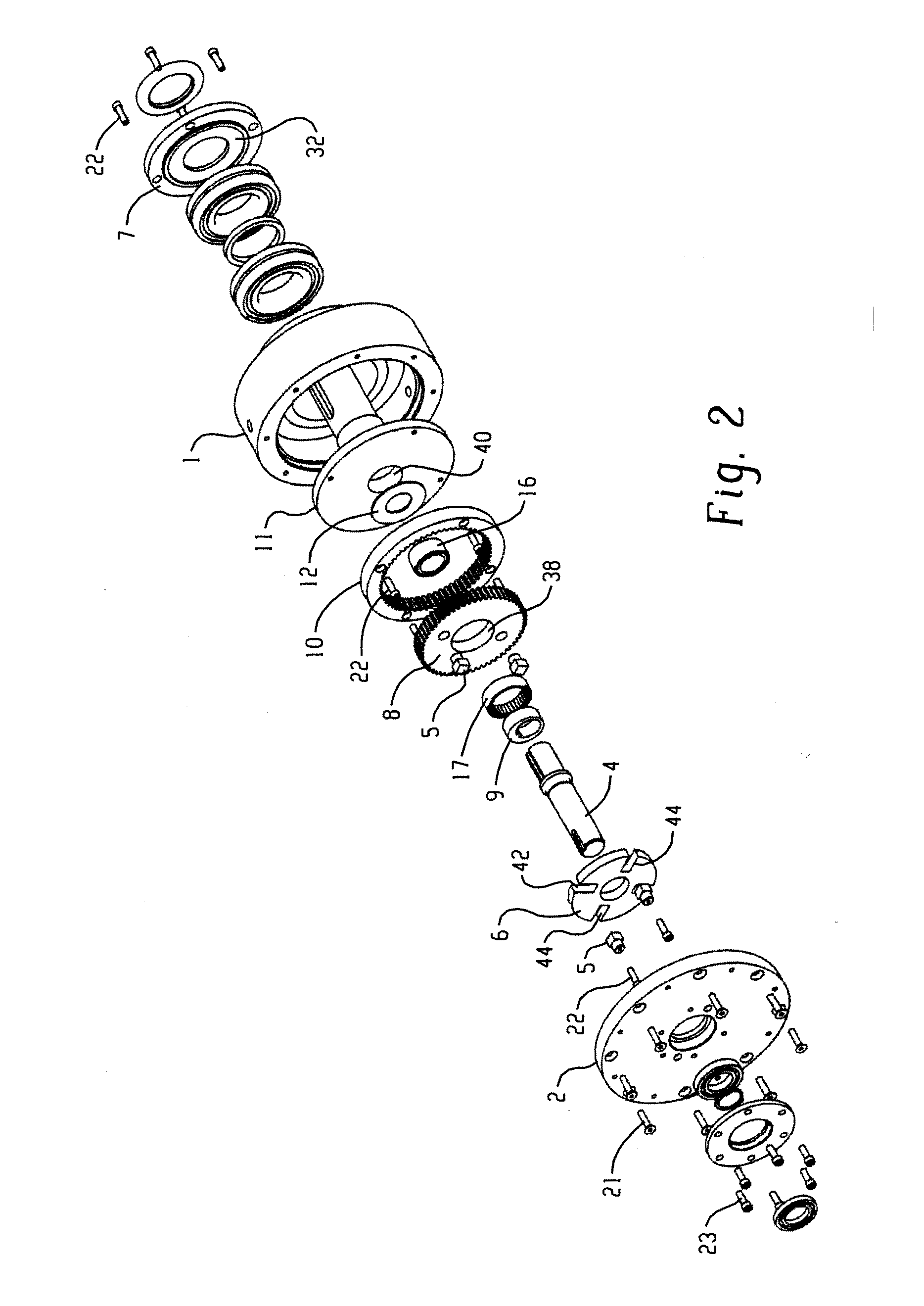
[0037]Shown in FIGS. 1 and 2 is an exemplary embodiment of a speed increaser of the present disclosure....


PUM


Abstract

A speed increaser is disclosed that translates slow rotating, high torque motion to high rotation, low torque motion and is suitable for use in a device like a wind turbine. The speed increaser has certain advantages, such as reduced weight and/or size compared to other units having the same performance characteristics. The speed increaser employs an externally toothed spur gear orbiting in a non-rotating manner inside an internally toothed ring gear. The input drives the ring gear and the orbiting spur gear drives an eccentric on the output shaft. In one embodiment, cross guide projections on the spur gear and cross guide projections on the housing engage slots in a swash plate. In another embodiment, cross guide projections on one side of a swash plate engage slots in the housing and cross guide projections on the opposite side of the swash plate engage slots in the orbiting spur gear; and, hardened wear plates and lubricant passages are provided on the swash plate cross guide projections. In another embodiment, the speed increaser housing includes an electric generator with the rotor driven by the speed reducer output shaft. In another version, the speed increaser and generator are housed within the hub of a fluid turbine impeller. In another version of the speed reducer, multiple output shafts are driven by the orbiting spur gear.

Description

[0001]This application claims the benefit of U.S. Provisional Application Ser. No. 61 / 103,424, filed Oct. 7, 2008, entitled SPEED REDUCER, by Michael E. WINIASZ, the disclosure of which is incorporated herein by reference in its entirety.BACKGROUND[0002]The present disclosure relates to a speed increaser that is suitable for use on motors and / or turbines, such as a wind turbine, for converting slow rotating, high torque motion into high rotation, low torque motion. The present disclosure can also be described as a planocentric gearbox.[0003]Presently, gear boxes for wind turbine applications are complex multi-stage gearing arrangements which are not only bulky and heavy but quite difficult to service when installed on the wind turbine tower. For example, a presently available 600 kilowatt commercially available wind turbine gear box weighs about 8,600 pounds or approximately 77 watts per pound.[0004]It has thus been desired to provide a way or means of reducing the complexity, size ...

Claims


Application Information

Patent Timeline
Patent Type & Authority Applications(United States)
IPC IPC(8): F03D9/00F16H1/32F16H57/04
CPCF03D11/00F05B2260/4031F05B2260/40311F16H1/32Y02E10/722H02K7/116H02K7/1823H02K7/183F16H57/0486F03D80/00Y02E10/72F03D9/25F03D15/10
Inventor WINIASZ, MICHAEL E.
Owner ADI WIND
Why Eureka
Try Eureka