Front structure for vehicle

Inactive Publication Date: 2010-04-08
TOYOTA JIDOSHA KK
View PDF2 Cites 9 Cited by
  • Summary
  • Abstract
  • Description
  • Claims
  • Application Information

AI Technical Summary

Benefits of technology

[0015]The present invention is constructed such as to include a rotation restricting member which restrains the transverse and longitudinal members from rotating in such a direction as to relatively approach each other but permits the transverse and longitudinal members to rotate in such a d

Problems solved by technology

In a collision mode where a local load is directly fed to a part of the front frame in the above-mentioned structure, however, the front frame may bend, thus failing to efficiently transmit and disperse the collision load to the side frames.
Though the bonding strength between the front frame and side frames may be enhanced for

Method used


Image

  • Front structure for vehicle
  • Front structure for vehicle
  • Front structure for vehicle

Examples


Embodiment Construction

[0029]In the following, preferred embodiments of the present invention will be explained in detail with reference to the drawings. In the drawings, the same or equivalent parts will be referred to with the same signs.

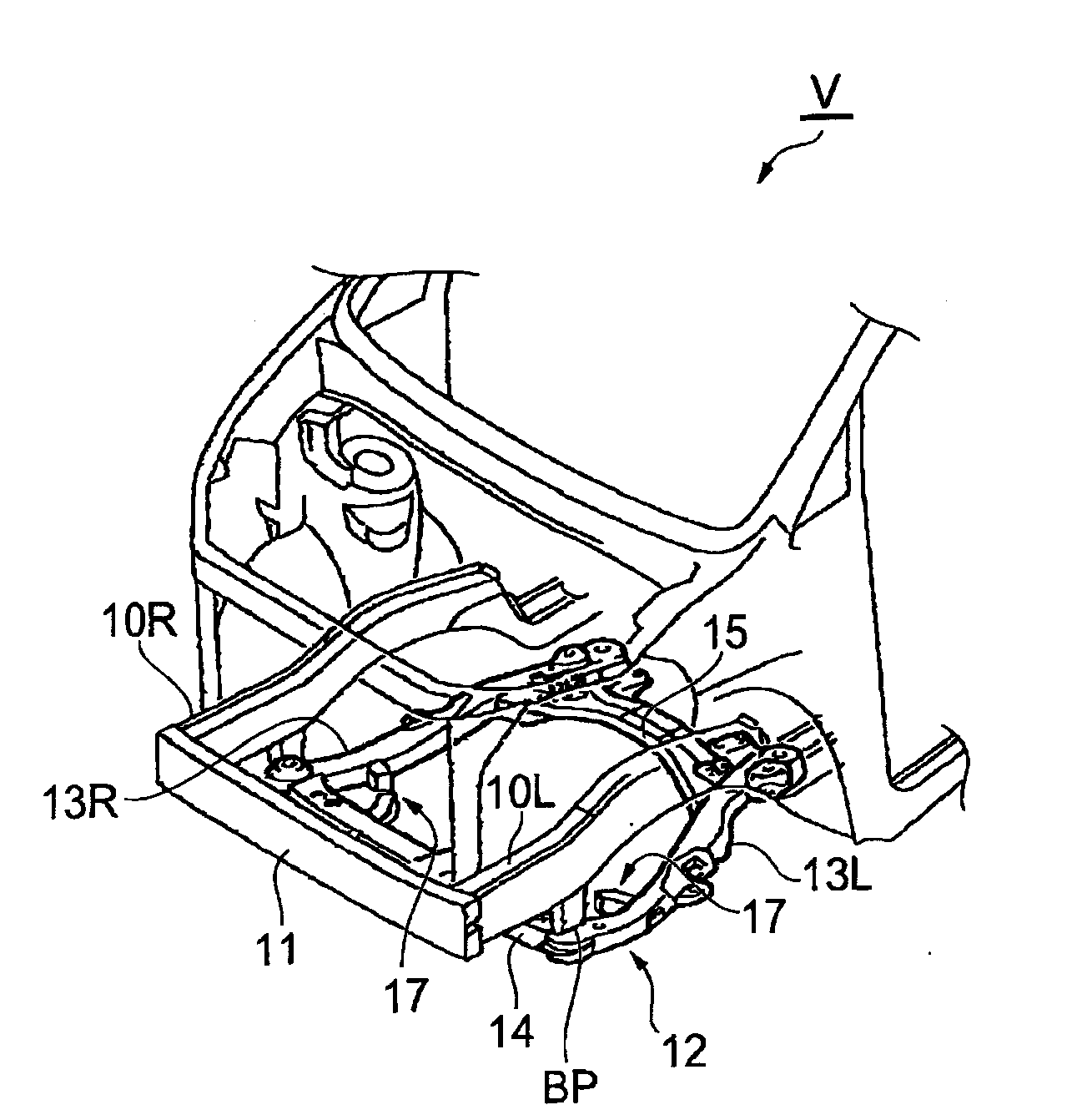
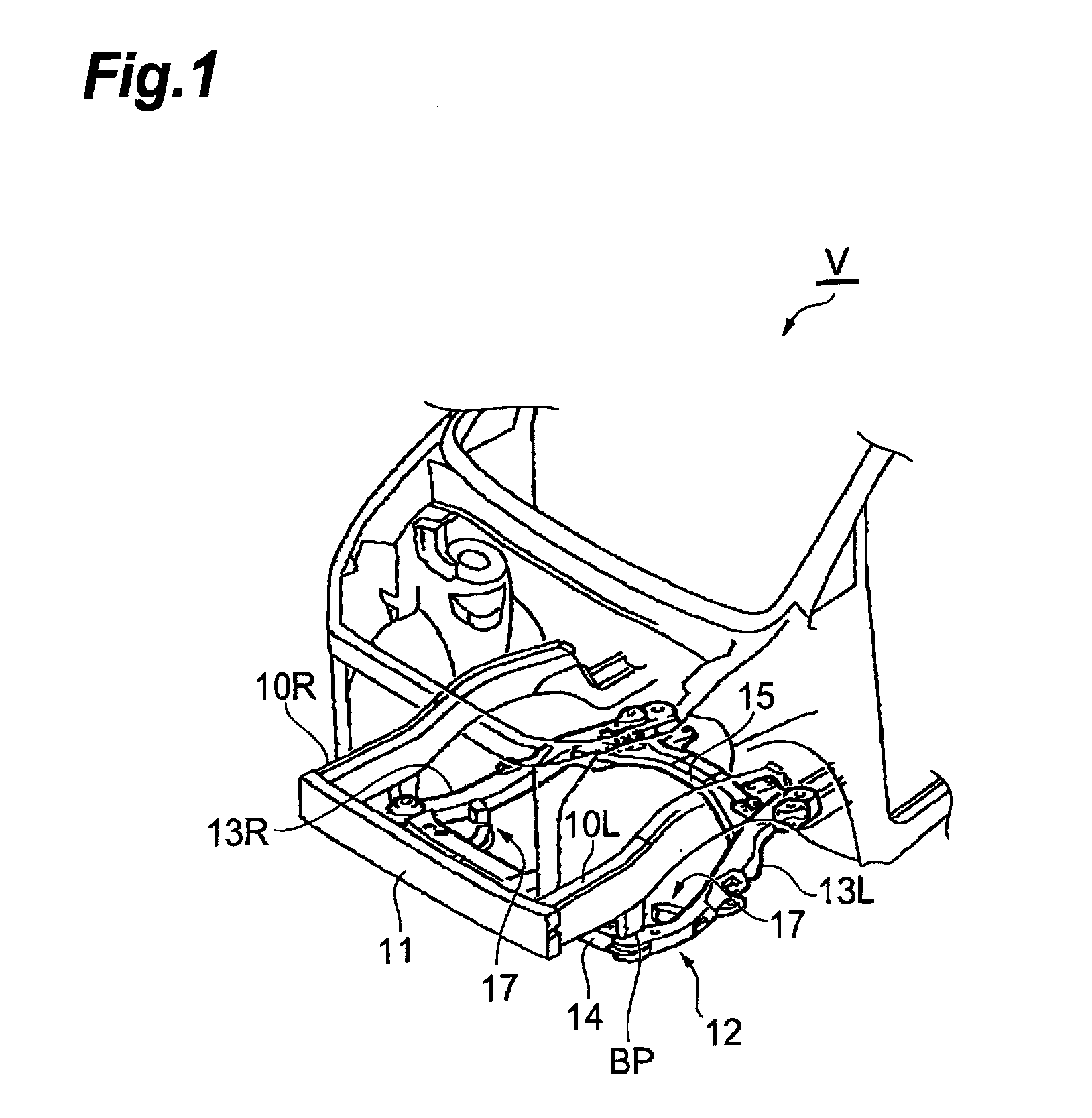
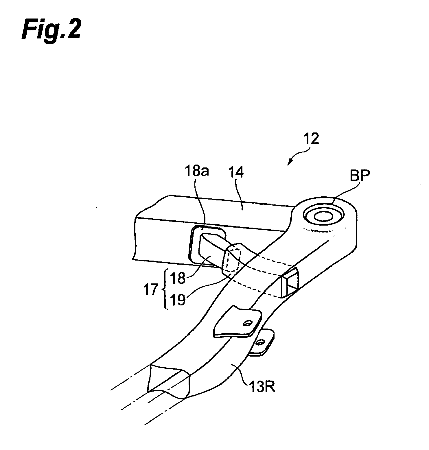
[0030]To begin with, the vehicle front structure in accordance with the first embodiment will be explained with reference to FIGS. 1 to 4. A case where the present invention is employed in a subframe of a vehicle will be explained here by way of example. FIG. 1 is a perspective view showing a skeleton structure of the vehicle including the subframe. FIG. 2 is a view showing a load transmission member constituting the subframe. FIGS. 3(a) and (b) are views for explaining an action in a case where a local load is fed to a front frame, whereas FIG. 4 is a view for explaining an action in a case where a collision load is fed to a side frame. By defining the forward direction of a vehicle advancing straightforward as “front”, the present specification uses terms representing...


PUM


Abstract

The object of the present invention is to provide a vehicle front structure which can efficiently absorb collision energy regardless of collision modes. In the vehicle front structure of the present invention, a load transmission member arranged on inner side faces of a front corner part of a subframe has a load transmission member male attached to a front frame and a load transmission member female attached to a side frame. In a collision mode where a local load is fed to the front frame, the load transmission member male and load transmission member female engage with each other, whereby the front frame is restrained from rotating in such a direction as to approach the side frame, while the fed collision load is transmitted to the side frame through the load transmission member. In a collision mode where a collision load is fed onto an axis of the side frame, on the other hand, the load transmission member male and load transmission member female separate from each other, whereby the load transmission through the load transmission member is blocked.

Description

TECHNICAL FIELD[0001]The present invention relates to a vehicle front structure.BACKGROUND ART[0002]Japanese Patent Application Laid-Open No. 2003-182625 discloses a vehicle front structure including a subframe constituted by a pair of left and right side frames extending in the front-to-rear direction of the vehicle, a front frame connecting the respective front end parts of the pair of left and right side frames, respective bifurcated parts formed at the rear side parts of the side frames so as to be curved inward in the vehicle width direction, and a rear frame transversely bridged between the left and right bifurcated parts.[0003]This vehicle front structure forms not only a path by which an offset collision load fed to one side frame is transmitted from the bifurcated part to a floor skeleton member through a rear mount part, but also a path by which the offset collision load is transmitted to the other side frame through the rear frame, thereby efficiently transmitting and dis...

Claims


Application Information

Patent Timeline
IPC IPC(8): B62D21/15
CPCB62D21/11B62D25/082B62D21/155B62D21/00B62D21/15B62D25/20
Inventor TAMAKOSHI, KOJI
Owner TOYOTA JIDOSHA KK
Why Eureka
Try Eureka