
Method and system for surgical planning

a surgical planning and surgical technology, applied in the field of surgical planning, can solve the problems of long and more traumatic surgeries, difficult selection of implants for fit and filling with acetate, and little effort to accurately determine the ideal position of implants prior to surgery

Active Publication Date: 2010-04-08
FUJIFILM CORP +1
View PDF17 Cites 38 Cited by
  • Summary
  • Abstract
  • Description
  • Claims
  • Application Information

AI Technical Summary

Problems solved by technology

Unfortunately, many current planning techniques rely on two-dimensional acetate portrayals of a prosthetic devise implanted which is then overlaid on the patient's two-dimensional x-ray.
Acetabular templating is mostly performed to determine the approximate size of the acetabular component, but there is little effort to accurately determine the ideal position of the implant prior to surgery.
Even implant selection for fit and fill with acetates can be problematic since the subject's x-ray may be rotated compared to the ideal view plane assumed when the acetate was created.
Discrepancies in implant size and placement which remain undetected during planning can lead to longer and more traumatic surgeries as originally intended prosthesis are removed and alternative prosthesis are used to correct mis-alignments which only become apparent after the operation has begun.
Many discrepancies between the desired and actual implant placement can go unnoticed, possibly resulting in reduced range of motion, impingement and subsequent dislocation, or premature joint wear.
Dislocation of a total hip replacement causes significant distress to the patient and physician and is associated with significant additional costs in order to relocate the hip.
Another complication of THR surgery is impingement between the neck of the femoral implant and the rim of the acetabular component.
Impingement can lead to advanced wear of the acetabular rim resulting in polyethylene wear debris shown to accelerate loosening of implant bone interfaces.
In certain cases, impingement may result in dislocation.
While this 2D slice can be scaled and rotated electronically, the physician is not assured of choosing the correct rotation or orientation.

Method used


Image

  • Method and system for surgical planning
  • Method and system for surgical planning
  • Method and system for surgical planning

Examples


Embodiment Construction

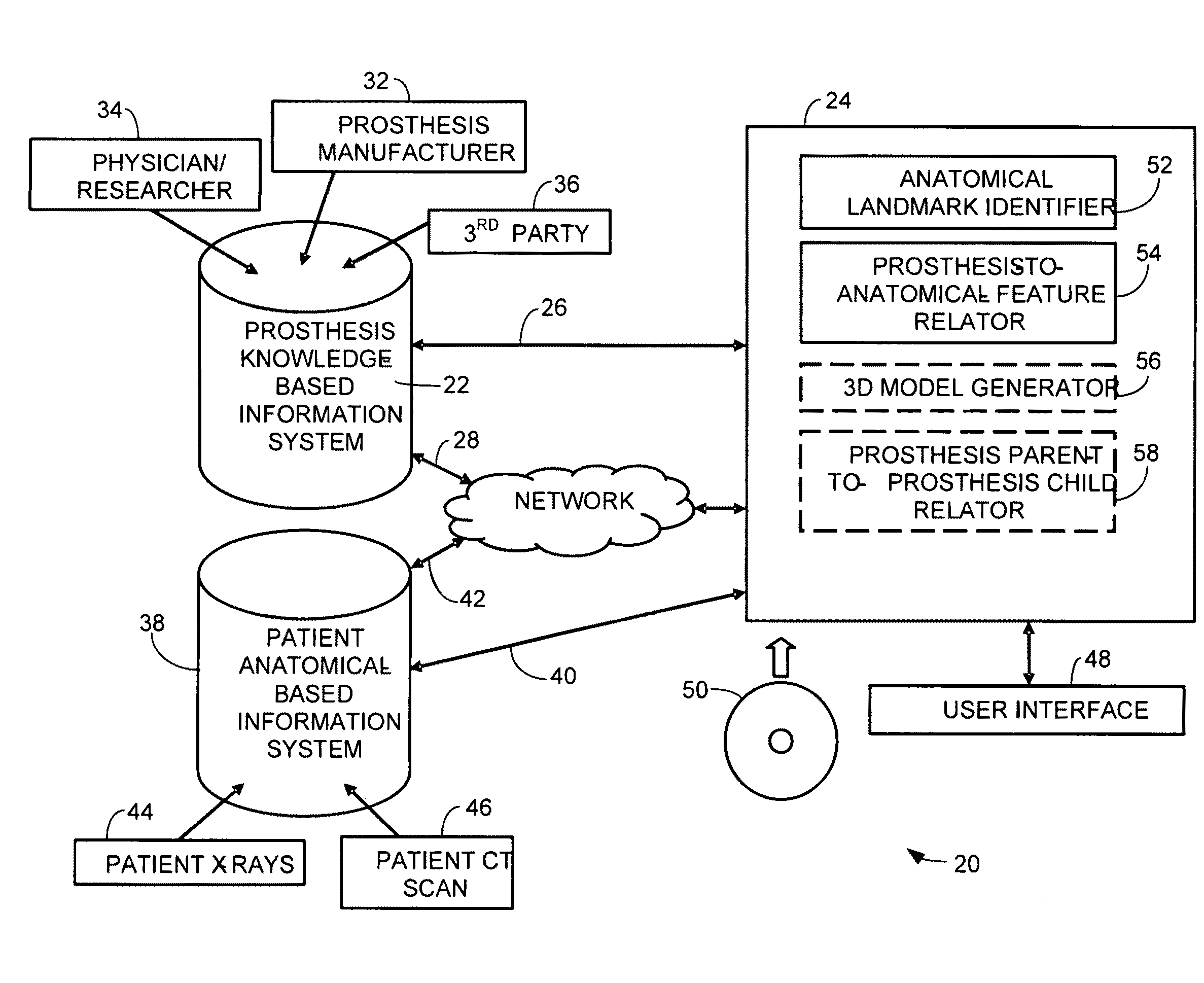
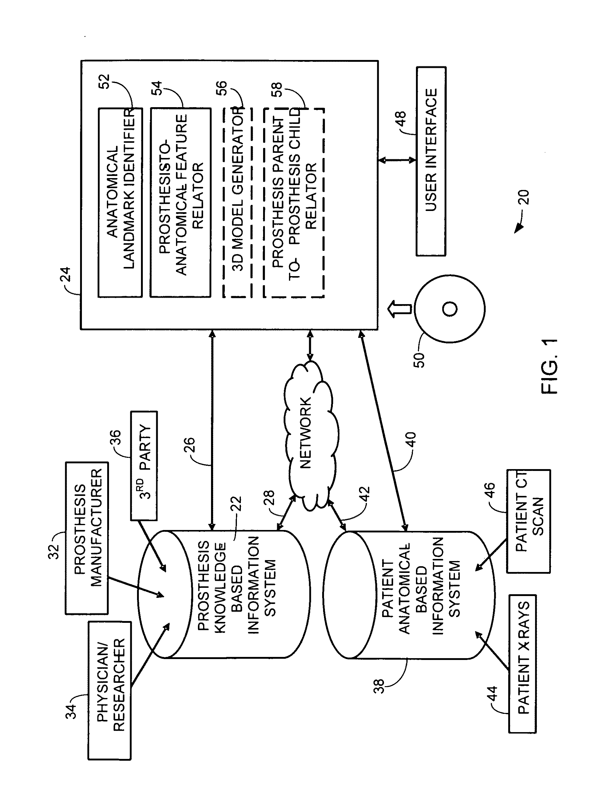
[0024]FIG. 1 schematically illustrates one embodiment of a system 20 for surgical planning. The system 20 has a prosthesis knowledge-based information system 22. In some embodiments, the prosthesis knowledge-based information system 22 may be a stand-alone database or set of machine-readable files which are directly accessible 26 or remotely accessible 28, for example via a network 30, by the system's controller 24. In other embodiments, the prosthesis knowledge-based information system 22 may be a locally or internally available database or set of machine readable files. The prosthesis knowledge-based information system 22 may exist on a variety of computer readable media, including, but not limited to, randomly accessible memory (RAM), read-only memory (ROM), re-writeable flash memory, magnetic media, and optically readable / writeable media such as CD's and DVD's, or any combination thereof. The one or more computer readable media for the prosthesis knowledge-based information syst...


PUM


Abstract

A method for surgical planning is disclosed. A set of related two-dimensional (2D) anatomical images or 3D images is displayed. A plurality of anatomical landmarks are identified on the set of anatomical images. A three-dimensional (3D) representation of a parent prosthesis is scaled to match a scale of the 2D anatomical images based at least in part on a relationship between the anatomical landmarks. A 2D representation of the scaled 3D parent prosthesis is displayed on at least one of the 2D anatomical images. A system for surgical planning is also disclosed. The system has a prosthesis knowledge-based information system, a patient anatomical-based information system, a user interface, and a controller. The controller has an anatomical landmark identifier. The controller also has a prosthesis-to-anatomical-feature relator. The controller is configured to display a set of related two-dimensional (2D) anatomical images from the patient anatomical-based information system on the user interface.

Description

TECHNICAL FIELD[0001]The claimed invention relates to methods for surgical planning, and more particularly to a method and system for surgical planning using a two-dimensional interface based on three-dimensional models and information.BACKGROUND OF THE INVENTION[0002]As the baby boomer generation ages, the number of hip replacement surgeries is expected to increase. In 2001, about 165,000 hip joints were replaced in U.S. hospitals according to the National Center for Health Statistics, and 326,000 knees were replaced. While the majority of joint replacement patients remain in the 60-plus year category, more people are deciding to have surgery one or two decades earlier.[0003]About 70 percent of people seeking hip replacement surgery have severe osteoarthritis, a common chronic disease that damages cartilage, a type of tissue that acts as a protective cushion allowing for the smooth, low-friction movement of the joint. Osteoarthritis is the leading cause of long-term knee damage and...

Claims


Application Information

Patent Timeline
Patent Type & Authority Applications(United States)
IPC IPC(8): G06G7/48G06K9/00
CPCA61B2019/502A61B2019/5295A61F2002/4633A61F2/46A61F2/32A61B2034/102A61B2090/367
Inventor ZUG, JAMES ANDREWFORSTEIN, MICAH AARONSARAGA, JR., EMIL MICHAEL
Owner FUJIFILM CORP
Learn More