Method of joining cable racks, and a splice plate

a technology of splicing plate and cable rack, which is applied in the direction of couplings, conveyors, rod connections, etc., can solve the problem of reducing the entire joining operation by half a time, and achieve the effect of reducing production costs

Inactive Publication Date: 2010-04-08
BURESUTO INDS
View PDF5 Cites 50 Cited by
  • Summary
  • Abstract
  • Description
  • Claims
  • Application Information

AI Technical Summary

Benefits of technology

[0016]In view of the above problems, it is an object of the present invention to provide a method of joining two cable racks together, which is capable of allowing the number of bolting positions on one side of the two cable racks to be reduced to two, and coping with cut-off of an end of the cable rack, while facilitating a reduction in production cost. It is another object of the present invention to provide a splice plate for use in the method.

Problems solved by technology

This also makes it possible to reduce by half a time of the entire joining operation and a problem in the joining operation.

Method used


Image

  • Method of joining cable racks, and a splice plate
  • Method of joining cable racks, and a splice plate
  • Method of joining cable racks, and a splice plate

Examples


first embodiment

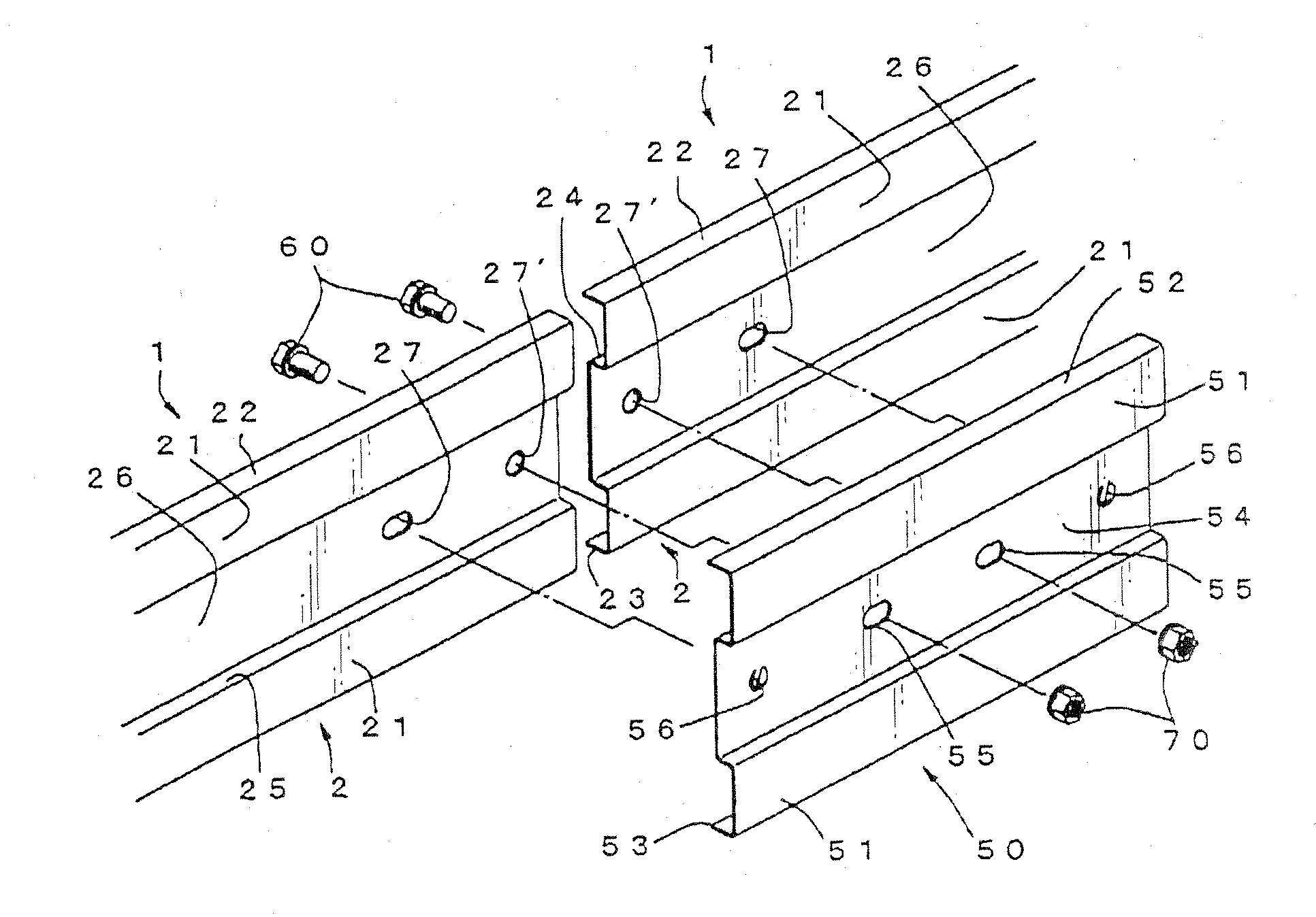
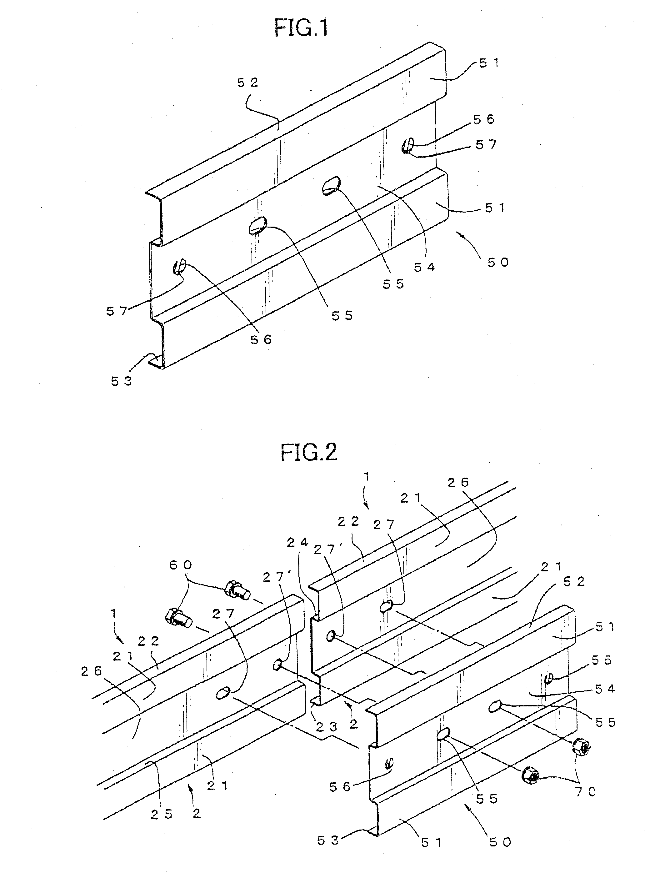
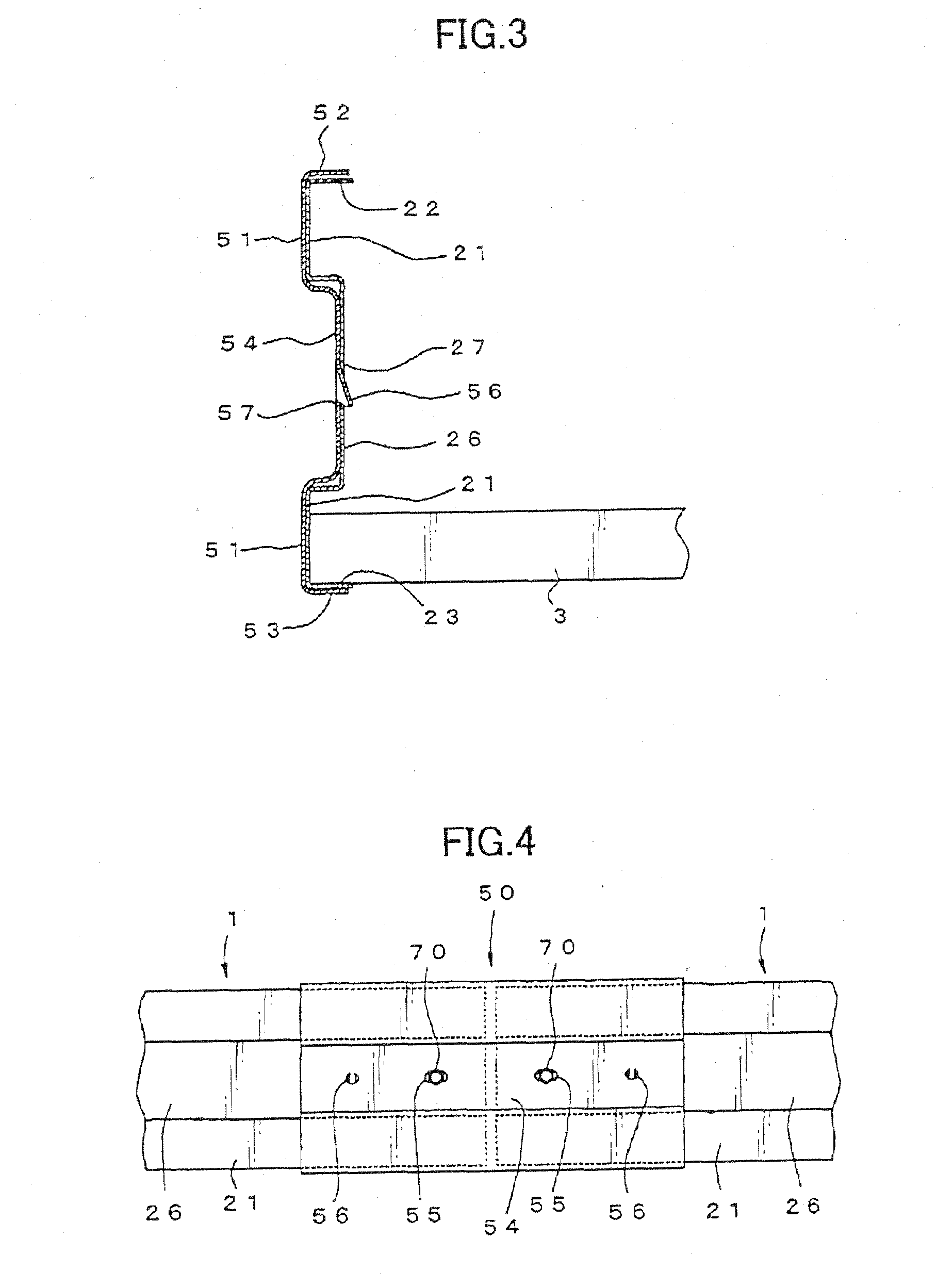
[0034]With reference to the drawings, the present invention will now be described based on an embodiment thereof. FIG. 1 shows a splice plate according to the present invention.

[0035]As already described in connection with FIG. 10, a cable rack 1 has a ladder-like structure in which two primary beams 2 extending in parallel relation to each other are connected together by a plurality of secondary beams 3 disposed therebetween at certain intervals. In order to ensure desired strength, each of the primary beams 2 has first and second bent edge plate portions 22, 23 extending from respective upper and lower edges of a vertically planar plate portion 21 inwardly in a direction perpendicular to the planar plate portion 21, and a vertically planar depressed plate portion 26 formed by depressing a generally vertically central region of the planar plate portion 21 inwardly in a manner continuous with an upper step portion 24 and a lower step portion 25.

[0036]The two primary beams 2 position...

second embodiment

[0052]FIG. 5 shows a splice plate 80 according to the present invention, wherein the splice plate 80 is designed to join together two cable racks different in height dimension of a primary beam, in a longitudinal direction thereof.

[0053]Specifically, the splice plate 80 has a vertically planar plate 81 having low and high planar plate portions which are formed to have different height dimensions each conforming to a corresponding one of a longitudinally-aligned pair of primary beams 2 in two racks 1, and arranged in a longitudinal direction thereof; two first bent plate edge portions 82a, 82b extending from respective upper edges of the low and high planar plate portions in such a manner as cover respective adjacent ends of the longitudinally-aligned pair of primary beams 2; a second bent plate edge portion 83 extending from a common lower edge of the low and high planar plate portions in such a manner as cover respective adjacent ends of the longitudinally-aligned pair of primary b...

third embodiment

[0055]FIG. 6 shows a splice plate 90 according to the present invention, wherein the splice plate 90 is designed to join together respective adjacent ends of each of two longitudinally-aligned pairs of primary beams 2 in two cable racks, in such a manner that a longitudinal-lateral plane (a longitudinal plane including a plurality of secondary beams of the cable rack) of one of the cable racks 1 is inclined relative to that of the other cable rack 1. The splice plate 90 has first and second portions formed integrally to extend outwardly from a central region thereof at a certain inclination angle relative to each other.

[0056]Specifically, the splice plate 90 has a vertically planar plate 91 having first and second planar plate portions which are formed integrally at a certain inclination angle relative to each other; two first bent plate edge portions 92 extending from respective upper edges of the first and second planar plate portions of the planar plate portion 91 in such a manne...


PUM

PropertyMeasurementUnit
lengthaaaaaaaaaa
strengthaaaaaaaaaa
thermal expansionaaaaaaaaaa

Abstract

Disclosed is a technique of joining two cable racks together in a longitudinal direction thereof. A splice plate is used which has two insertion holes each formed at a position corresponding to a first one of two joint holes in each of adjacent ends of each of two longitudinally-aligned pairs of primary beams of two cable racks, and two lock protrusions each formed at a position corresponding to the other second joint hole, in a manner engageable with the second joint hole. The adjacent ends of the longitudinally-aligned pair of primary beams are joined together by means of engagement between the lock protrusions of the splice plate and the second joint holes of the adjacent ends of the longitudinally-aligned pair of primary beams, and fastening between two bolt and two nuts through the first insertion holes and the insertion holes of the splice plate. Thus, two cable racks can be joined together by performing a bolting operation only at a single position in each of the adjacent ends of the longitudinally-aligned pair of primary beams. This makes it possible to reduce by half a time of joining operation while suppressing a trouble in the joining operation.

Description

BACKGROUND OF THE INVENTION[0001]1. Field of the Invention[0002]The present invention relates to a method of joining two cable racks together in a longitudinal direction thereof, and a splice plate for use in the method.[0003]2. Description of the Background Art[0004]In various architectural structures, such as office buildings, industrial plants and station buildings, cable racks are set up to allow a cable to be laid out therealong. This type of cable racks have a ladder-like structure in which two primary beams extending in parallel relation to each other are connected together by a plurality of secondary beams disposed therebetween at certain intervals. Commercially-available cable racks are limited to several types each having a given length. Thus, when it is necessary to lay out a cable over a long distance, a plurality of cable racks are used by joining them together in a longitudinal direction thereof.[0005]In such a case, a splice plate 30 having a configuration as shown in...

Claims


Application Information

Patent Timeline
Patent Type & Authority Applications(United States)
IPC IPC(8): F16B5/02B23P11/00F16B5/00
CPCF16B7/182H02G3/0456Y10T403/5741Y10T29/49948H02G3/0608
Inventor FUNAHASHI, JUNIBAYASHI, TADAYOSHIKADOWAKI, JUNMATSUKAWA, KOJIASATSUMA, EISAKUKATO, JUNICHISHIBATA, JUNPEIKITAJIMA, AKIHIROABE, TOSHIHIKOSAKAMOTO, SEIICHIUCHIYAMA, KOJIHARIKAGO, HIROSHIMENG, ZHANG
Owner BURESUTO INDS
Why Eureka
Try Eureka