Mechanical Embolectomy Device and Method

a technology of embolism and occlusion, applied in the field of mechanical embolism device and method, can solve the problems of limited utility of patients with large clots, limited use of tpa therapy, and significant time constraints of tpa therapy, so as to improve the appreciation of the contribution to the art

Inactive Publication Date: 2010-04-08
RAZACK NASSER
View PDF45 Cites 95 Cited by
  • Summary
  • Abstract
  • Description
  • Claims
  • Application Information

AI Technical Summary

Benefits of technology

[0014]There has thus been outlined, rather broadly, the more important features of the invention in order that the detailed description thereof that follows may be better understood and in order that the present contribution to the art may be better appreciated.
[0015]Numerous objects, features and advantages of the present invention will be readily apparent to those of ordinary skill in the art upon a reading of the following detailed description of presently preferred, but nonetheless illustrative, embodiments of the present invention when taken in conjunction with the accompanying drawings. The invention is capable of other embodiments and of being practiced and carried out in various ways. Also, it is to be understood that the phraseology and terminology employed herein are for the purpose of descriptions and should not be regarded as limiting.

Problems solved by technology

The goal of therapy is to restore perfusion to the ischemic but potentially salvageable brain tissue rather than to the irreversibly damaged brain tissue, since re-establishing blood flow to such damaged tissue can cause complications such as hemorrhage.
Most patients with acute ischemic stroke have thromboembolic material occluding large cerebral vessels and hence disruption of cerebral blood flow.
This treatment is suitable for smaller clots, but has limited utility for patients with large clots, such as are often present in acute occlusions of the internal carotid artery (ICA), proximal middle cerebral artery (MCA), and basilar artery (BA).
Also, TPA therapy has significant time constraints, and is generally effective only if given within 3-6 hours of stroke symptom onset.
Contraindications to TPA and these time constraints led to mechanical embolectomy.

Method used


Image

  • Mechanical Embolectomy Device and Method
  • Mechanical Embolectomy Device and Method
  • Mechanical Embolectomy Device and Method

Examples


Embodiment Construction

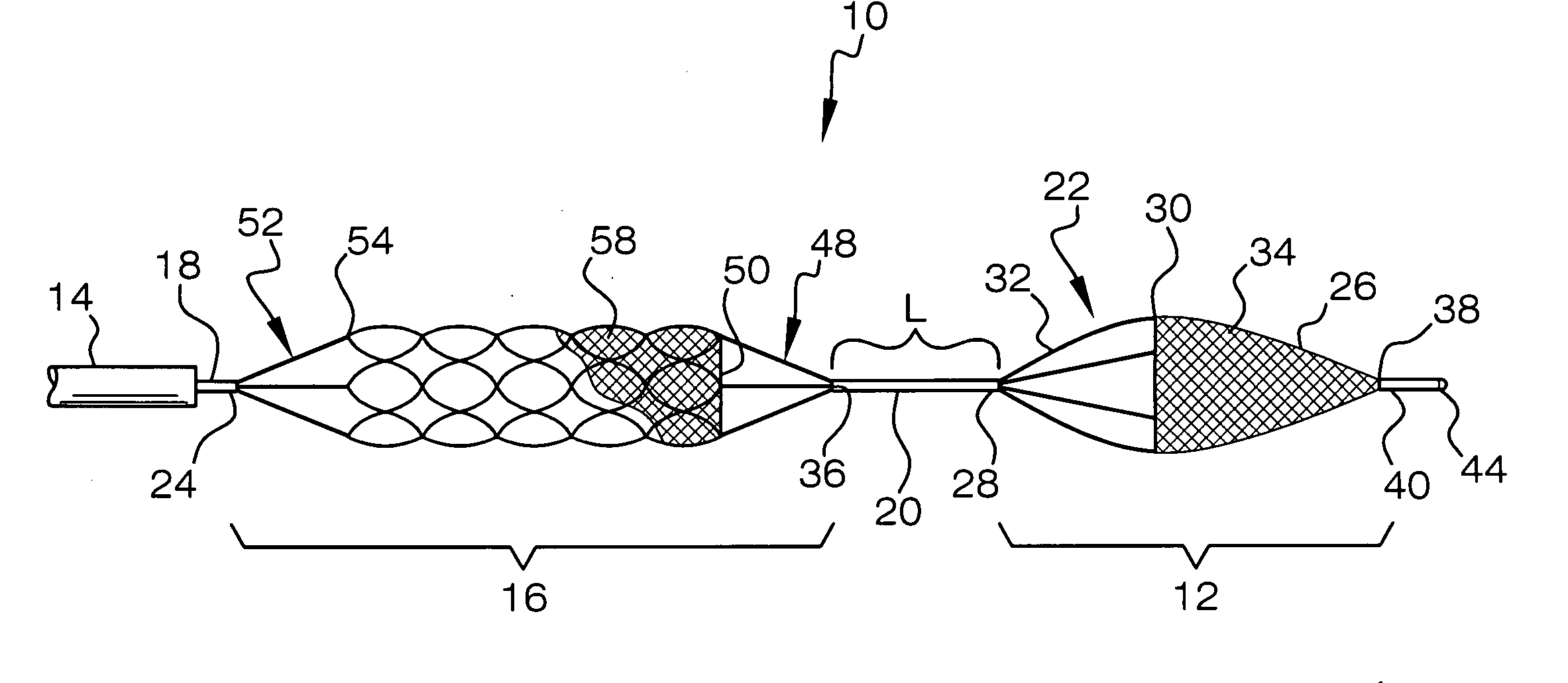
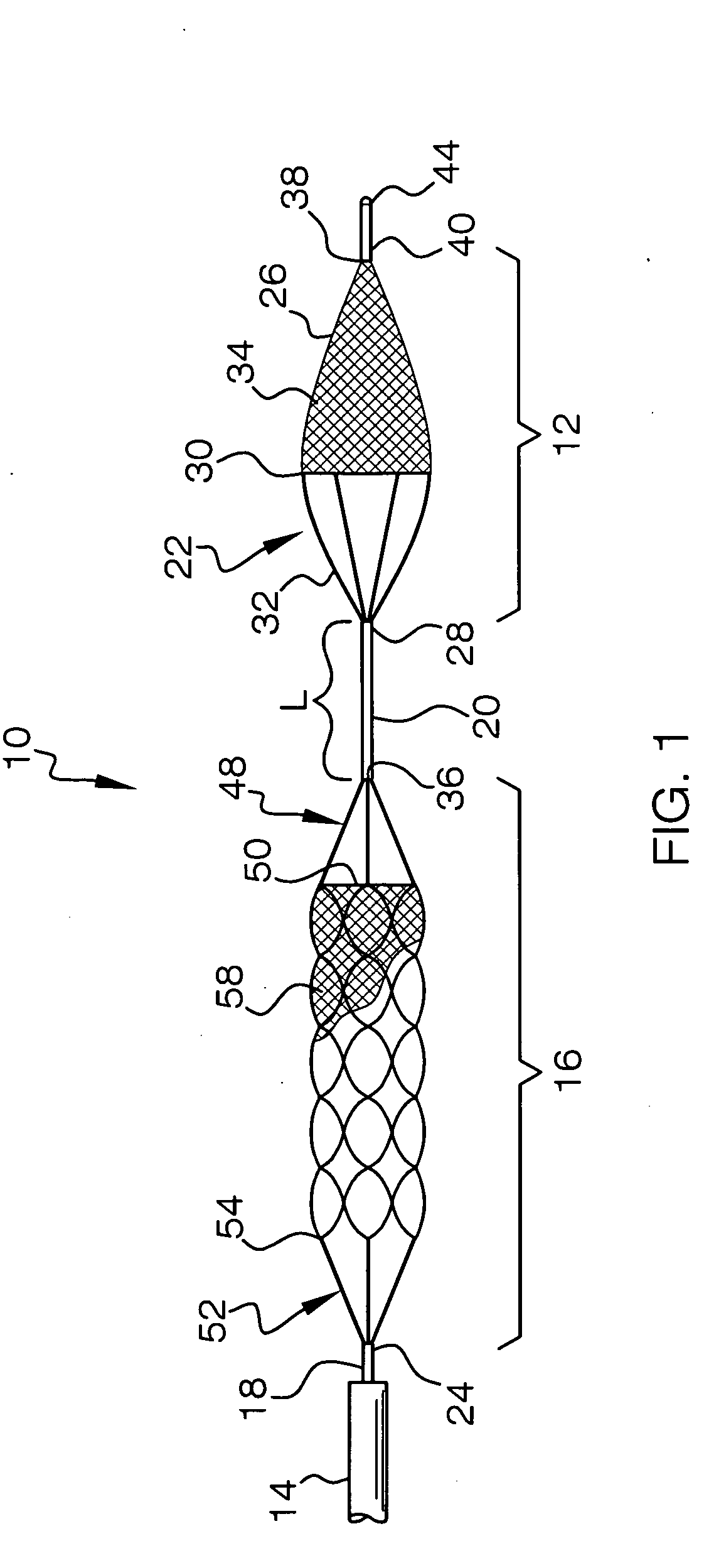
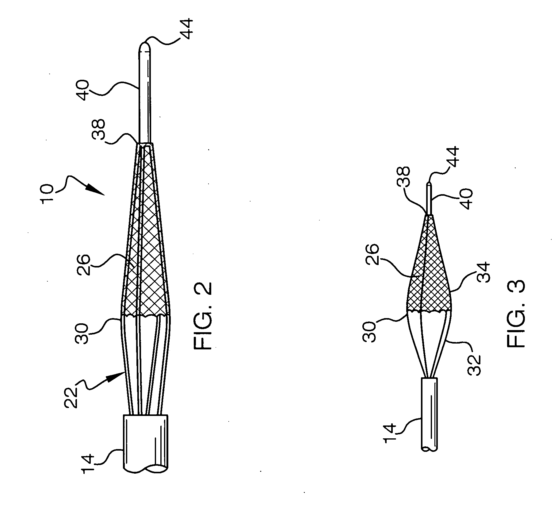
[0025]There is shown in FIGS. 1-5 an embolectomy device 10 according to the invention. In FIG. 1, the embolectomy device 10 is shown fully extended. In FIGS. 2-5, the embolectomy device 10 is shown partially extended in various stages. The embolectomy device 10 is positionable in and movable within a catheter 14, such as a microcatheter. The embolectomy device 10 includes an elongated shaft such as proximal wire 18 extending through an opening in the microcatheter 14, an expander portion 16, and a retrieval portion 12. The proximal wire 18 can have a proximal end (not shown) and distal end 24. The expander portion 16 can be provided at the distal end 24 of the proximal wire 18. The retrieval portion 12 can be provided distally at a spaced distance from the expander portion 16, and can be connected to the expander portion by an intermediate elongated shaft or intermediate connecting wire 20.

[0026]The retrieval portion 12 may be formed from or attached to the intermediate connecting w...


PUM


Abstract

An embolectomy device includes an elongated shaft positionable in and movable within a catheter. The elongated shaft having a distal end portion. An expander portion having proximal and distal ends. The expander portion having a first plurality of legs connecting the proximal end of the expander portion to the distal end portion of the elongated shaft and a second plurality of legs connecting the distal end of the expander portion to the proximal end of the intermediate elongated shaft. The expander portion being biased to expand laterally outward from the long axis of the embolectomy device when the expander portion has been moved out of the catheter to engage a clot. A retrieval portion can be provided proximally of the expander portion. A retrieval net can be fixed to the retrieval portion. The expander portion can be at least partially covered by a net. A method for removing clots and other occlusions for body canals is also provided.

Description

FILED OF THE INVENTION[0001]The present invention relates generally to embolectomy, and more particularly, relating to a mechanical embolectomy device including a clot expander and a clot particle retriever, and method of using the same.BACKGROUND OF THE INVENTION[0002]There are currently in excess of 700,000 new or recurrent strokes every year in the United States. It is the third leading cause of death in the United States after coronary artery disease and cancer. Approximately 40% (>250,000) of strokes are due to large vessel occlusion, potentially requiring a device for treatment.[0003]Treatment must begin with an evaluation of the patient. Diagnostic neuroimaging is used to obtain noninvasive real-time information about the patient. The goal of therapy is to restore perfusion to the ischemic but potentially salvageable brain tissue rather than to the irreversibly damaged brain tissue, since re-establishing blood flow to such damaged tissue can cause complications such as hem...

Claims


Application Information

Patent Timeline
Patent Type & Authority Applications(United States)
IPC IPC(8): A61M29/00
CPCA61B17/221A61B17/32075A61M25/104A61B2017/320741A61F2/013A61B2017/22001
Inventor RAZACK, NASSER
Owner RAZACK NASSER
Why Eureka
Try Eureka