Fuel delivery system for a turbine engine

a technology of fuel delivery system and turbine engine, which is applied in the direction of machines/engines, combustion types, lighting and heating apparatus, etc., can solve the problems of large transient temperature variation and associated pressure disturbance, premature failure of components, and adversely affecting the gas turbine as a whole, so as to reduce emissions

Inactive Publication Date: 2010-04-15
PW POWER SYST LLC
View PDF12 Cites 23 Cited by
  • Summary
  • Abstract
  • Description
  • Claims
  • Application Information

AI Technical Summary

Benefits of technology

[0006]A fuel injector of a fuel delivery system for a gas turbine engine of the present invention reduces emissions by premixing fuel and air in a fuel lean concentration near the weak extinction limit prior to combustion, and by providing uniformity of a fuel air mixture within the combustion system. The system achieves this uniformity by ensuring that any pressure disturbances within the combustion chamber affect the flow of fuel and air substantially equally.

Problems solved by technology

As a result, small variations or perturbations in fuel-air ratio within the combustor can produce large transient temperature variations and associated pressure disturbances.
Unfortunately, high pressure oscillations in the combustion chamber can create high vibratory stress upon the combustion chamber components causing premature failure of the components that can adversely affect the gas turbine as a whole.

Method used


Image

  • Fuel delivery system for a turbine engine
  • Fuel delivery system for a turbine engine
  • Fuel delivery system for a turbine engine

Examples


Embodiment Construction

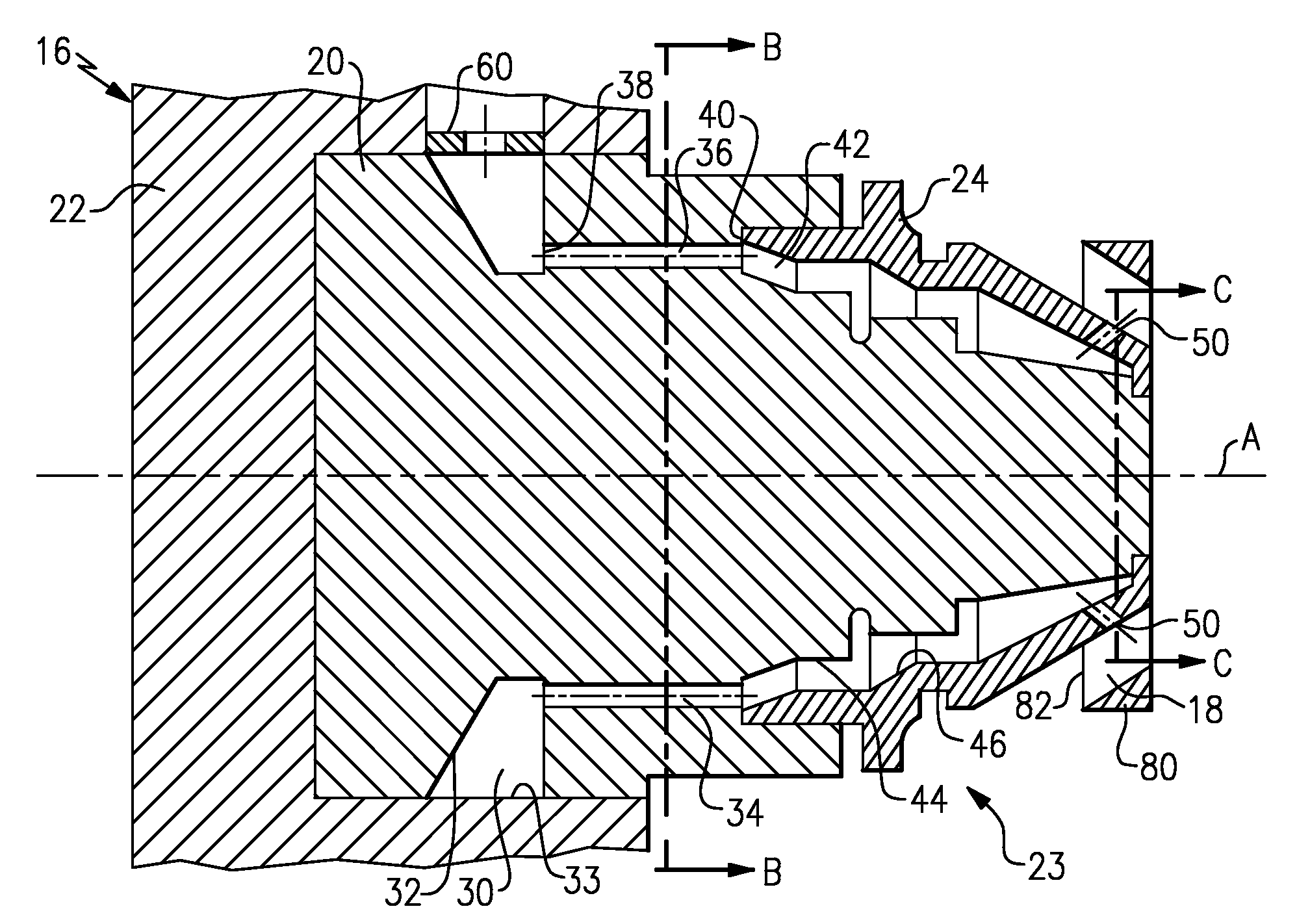
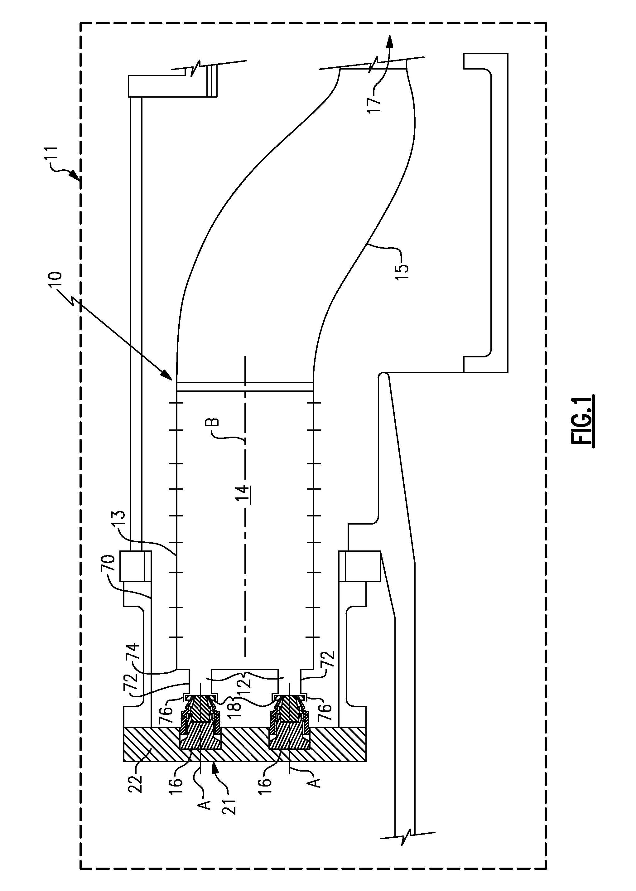
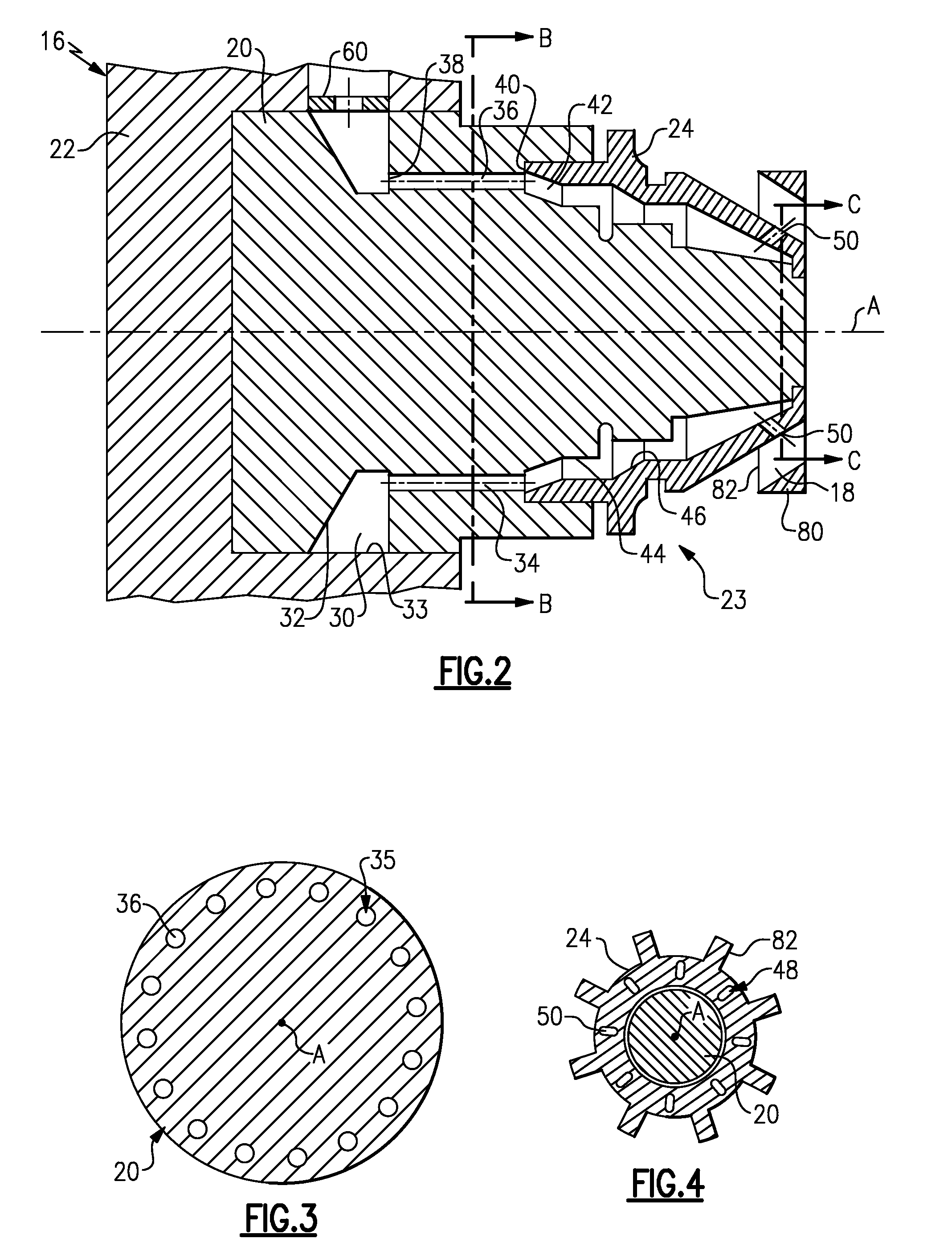
[0018]In FIG. 1 of the present invention, a turbine engine 11 that may be of a gas type has a plurality of circumferentially spaced combustors 10 that each extend generally along respective centerlines B. Each combustor 10 has an encasement 70 that generally supports a fuel delivery system 21 and houses a tubular structure or liner 13 and a transition duct 15 of the combustor 10. The fuel delivery system 21 delivers a controlled fuel flow to fuel injectors 16 which inject the fuel into a premixing passage 12. The fuel injectors 16 also provide air inlet passages 18 which admit air into the premix passages 12 where the air and fuel premix before passing through an end flange 74 of the liner 13 and to a combustion chamber 14 defined by the liner 13 where the fuel-air mixture is burned. The resulting hot products and various gases flow downstream along centerline B in the direction of the transition duct 15, through the transition duct and into the turbine section of the engine in the ...


PUM


Abstract

A fuel delivery system for a turbine engine has at least one fuel injector having an upstream orifice arrangement that produces a first pressure drop of flowing fuel and a downstream orifice arrangement that produces a second pressure drop of the flowing fuel. The upstream orifice arrangement or the downstream orifice arrangement includes a noncylindrical orifice.

Description

BACKGROUND OF THE INVENTION[0001]The present invention relates to a fuel delivery system for a gas turbine engine and, more particularly, to an emission reducing fuel injector of the fuel delivery system.[0002]Environmental concerns and standards, generally enforced by increasingly stringent government regulations, require relatively low exhaust emission levels from turbine engines such as the gas type. To assist in obtaining very low emission levels, a lean premix combustion process is commonly utilized. In this process, the fuel and air are mixed prior to combustion and burned close to the fuel-lean extinction limit. This premix process provides a sufficiently lean fuel-air concentration ratio in the reaction zone so that emission levels for nitrogen oxide generation are minimized upon combustion.[0003]In a lean premix system, fuel and air are mixed thoroughly in a premix passage prior to combustion. The requirements for very low NOx emissions demand fuel / air concentration ratios ...

Claims


Application Information

Patent Timeline
Patent Type & Authority Applications(United States)
IPC IPC(8): F02C7/22F23R3/28
CPCF23D11/106F23D11/38F23D14/48F23R2900/00014F23R3/28
Inventor TUTHILL, RICHARD S.
Owner PW POWER SYST LLC
Why Eureka
Try Eureka