Battery Pack Having Protection Circuit for Secondary Battery

a protection circuit and secondary battery technology, applied in safety/protection circuits, electrochemical generators, transportation and packaging, etc., can solve the problems of inaccurate detection of battery temperature and inability to perform accurate charge stop control

Active Publication Date: 2010-04-15
MITSUMI ELECTRIC CO LTD
View PDF4 Cites 35 Cited by
  • Summary
  • Abstract
  • Description
  • Claims
  • Application Information

AI Technical Summary

Benefits of technology

[0011]It is a general object of the present invention to provide a novel, useful and improved battery pack in which the above-mentioned problems are eliminated.
[0012]A more specific object of the present invention is to provide a battery pack, which can perform a temperature protection of a secondary battery, prevent self-heating when discharging, and which can perform an appropriate charge stop control.
[0015]According to the present invention, temperature protection of a secondary battery can be performed with high accuracy, self-heating when discharging can be prevented, and an appropriate charge stop control can be performed.

Problems solved by technology

However, because a predetermined voltage is applied to the battery pack shown in FIG. 2 from the charge device through the voltage-dividing resistor, there is a problem in that the temperature of the battery pack cannot be detected accurately and an accurate charge stop control cannot be performed if the predetermined voltage of the charge resistor varies or if there is an error in the voltage-dividing resistor of the charge device.

Method used


Image

  • Battery Pack Having Protection Circuit for Secondary Battery
  • Battery Pack Having Protection Circuit for Secondary Battery
  • Battery Pack Having Protection Circuit for Secondary Battery

Examples


Embodiment Construction

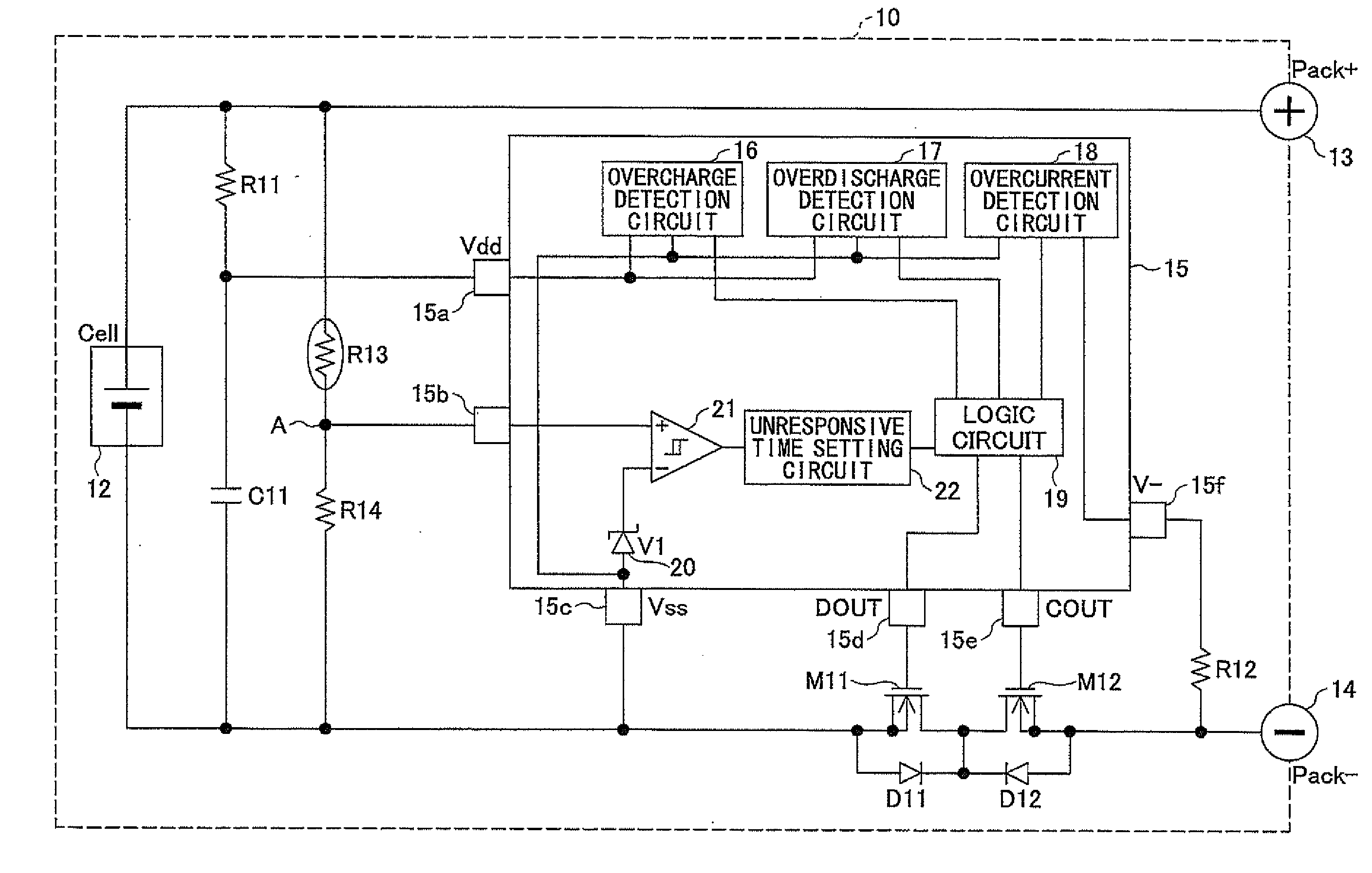
[0022]FIG. 3 is a block diagram of a battery pack to which the present invention is applied. In FIG. 3, a series circuit containing a resistor R11 and a capacitor C11 is connected in parallel to a lithium ion battery 12. A positive terminal of the lithium ion battery 12 is connected to an external terminal 13 of the battery pack 10 by wiring. A negative terminal of the lithium ion battery 12 is connected to an external terminal 14 of the battery pack 10 by wiring through n-channel MOS transistors M11 and M12 for current interruption.

[0023]Drains of the MOS transistors M11 and M12 are connected commonly. A source of the MOS transistor M11 is connected to the negative terminal of the lithium ion battery 12. A source of the MOS transistor M12 is connected to the external terminal 14. Body diodes D11 and D12 are connected equivalently between the sources and the drains of the MOS transistors M11 and M12, respectively.

[0024]A series circuit containing a thermistor R13 and a resistor 14 i...


PUM


Abstract

A battery pack has first through third external terminals connected to positive and negative power supply terminals and a voltage detection terminal, respectively. A secondary battery is connected between the first external terminal and the third external terminal. A protection circuit controls ON / OFF of first and second switching elements provided on a wiring between the secondary battery and a load or a charge device by detecting an overcharge, an overdischarge and an overcurrent of the secondary battery. A first thermistor is connected between the second external terminal and the third external terminal. A series circuit containing a second thermistor and a resistor is provided in parallel to the secondary battery. A third switching element is connected between the second external terminal and the third external terminal. The protection circuit turns on the third switching element and short-circuits between the second external terminal and the third external terminal when a detection is made by the second thermistor that a temperature of the secondary battery exceeds a predetermined temperature.

Description

FIELD OF THE INVENTION[0001]The present invention relates to a battery pack and, more particularly, to a battery pack equipped with a protection circuit for a secondary battery.BACKGROUND OF THE INVENTION[0002]In recent years, a lithium ion battery is mounted as a rechargeable battery to portable equipment such as a digital camera. Since the lithium ion battery is weak in overcharge and overdischarge, a battery pack is provided with a protection circuit for overcharging and overdischarging in many cases.[0003]FIG. 1 and FIG. 2 are block diagrams of conventional battery packs. In the battery pack 1 shown in FIG. 1, a series circuit containing a capacitor C1 and a resistor R1 is connected in parallel to a lithium ion battery 2. A positive terminal of the lithium ion battery 2 is connected to an external terminal 3 of the battery pack 1, and a negative terminal is connected to an external terminal 4 of the battery pack 1 through n-channel MOS (metal oxidization film semiconductor) tran...

Claims


Application Information

Patent Timeline
Patent Type & Authority Applications(United States)
IPC IPC(8): H02J7/00
CPCH01M10/443H01M10/486H02J2007/004H02J2007/0037H02J2007/0039H02J7/0031H02J7/00302H02J7/00304H02J7/00306Y02E60/10
Inventor TAKEDA, TAKASHITAKESHITA, JUNJI
Owner MITSUMI ELECTRIC CO LTD
Why Eureka
Try Eureka