
System and process for recording ERG, PERG and VEP multifocal electrofunctional responses in real-time

a multi-functional electrofunctional and real-time technology, applied in the field of ophthalmology, can solve the problems of lack of control of retinal and/or cortical areas really stimulated, requiring very long execution times, etc., and achieve the effect of eliminating uncertainties in measurement and improving quality control

Active Publication Date: 2010-04-15
C S O SRL
View PDF3 Cites 17 Cited by
  • Summary
  • Abstract
  • Description
  • Claims
  • Application Information

AI Technical Summary

Benefits of technology

[0006]Accordingly, it is an object of the present invention to provide a system and an apparatus that further improves quality control, thereby eliminating uncertainties in measurement due to the intrinsic variability of the result itself in conventional clinical practice.

Problems solved by technology

Although widely used in current ophthalmologic diagnosis, this technique has some limitations, the first of which is the lack of control of the retinal and / or consequently cortical areas really stimulated, and the instant feedback of the result of the bioelectric responses recorded.
However, it requires very long execution times and allows possible artifacts (biopotentials induced by loss of focus or movements of the patient's eyes) to be monitored but does not allow them to be quickly corrected.
Such a technique does, however, require waiting until the end of each cycle of each m-sequence for some repetitions, imposing long and pointless waiting times on the patient.

Method used


Image

  • System and process for recording ERG, PERG and VEP multifocal electrofunctional responses in real-time
  • System and process for recording ERG, PERG and VEP multifocal electrofunctional responses in real-time
  • System and process for recording ERG, PERG and VEP multifocal electrofunctional responses in real-time

Examples


Embodiment Construction

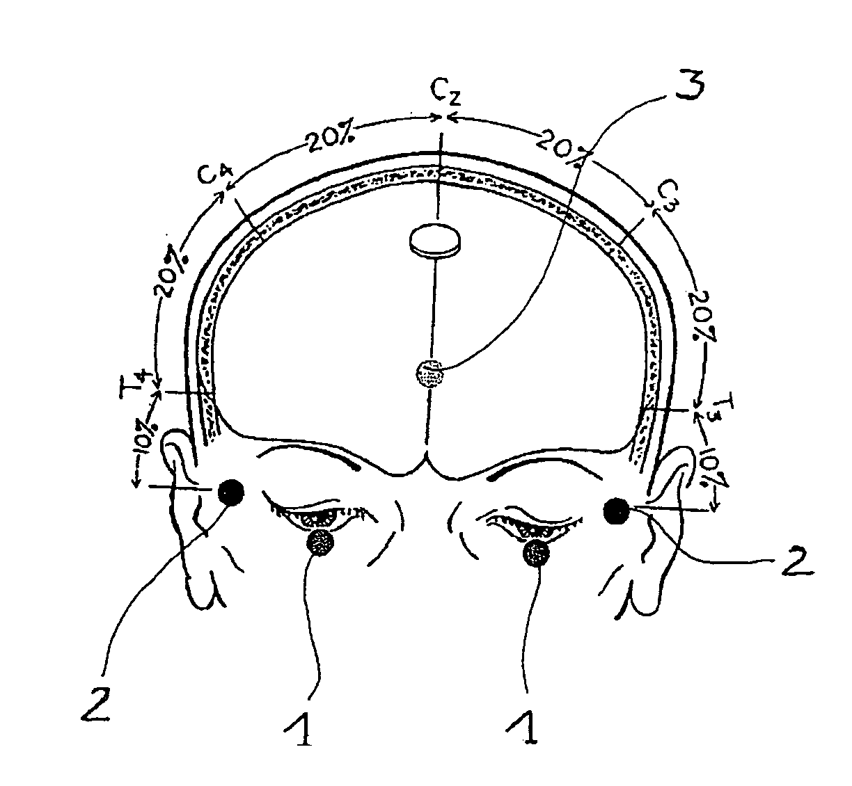
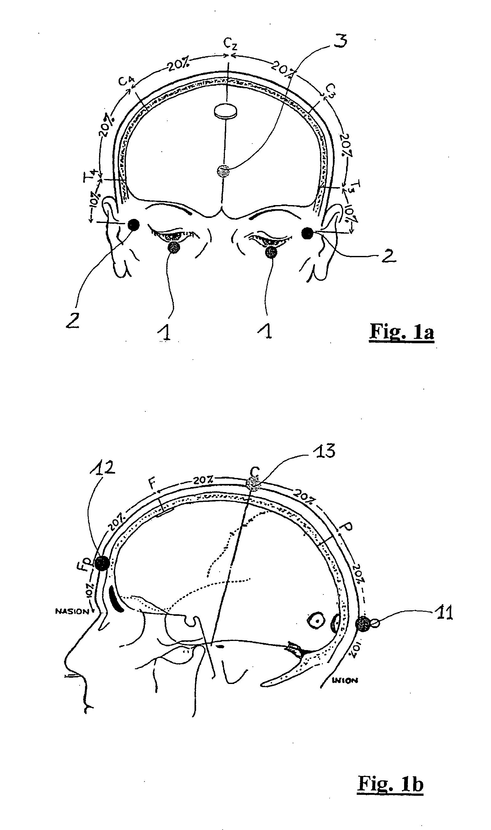
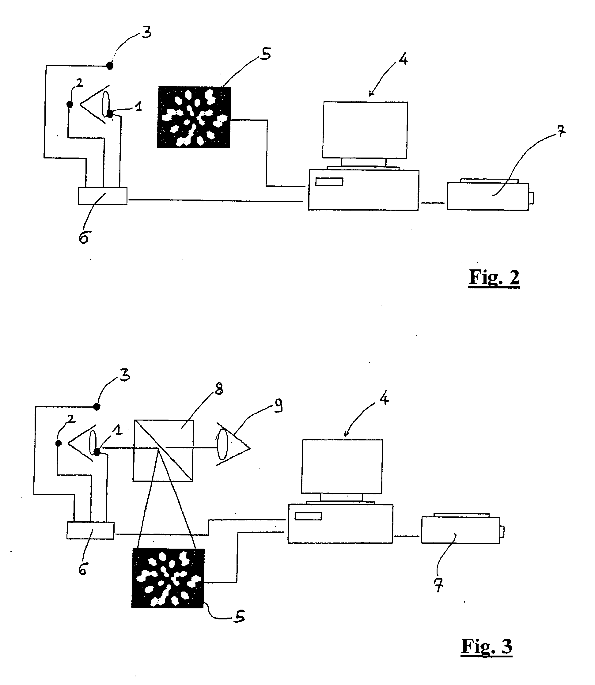
[0020]Referring now to the drawings and, more particularly, to FIGS. 1-5, there is shown generally a specific, illustrative system and process for recording ERG, PERG and VEP multifocal electrofunctional responses in real-time, according to various aspects of the present invention. In one embodiment, illustrated generally in FIGS. 1a, 1b, 2 and from 4a-4h, a configuration of electrodes is arranged on the face of a patient to be examined, as in conventional ERG, PERG and VEP recording techniques. Specifically, in case of retinal biopotential (FIG. 1a), an active exploring electrode is inserted inside the lower conjunctival fornix (positions 1) or on the corneal surface of each eye, the electrode coming into contact with the eyeball or also at the level of the central visual cortex using surface electrodes, so as to pick up a bioelectric signal generated by the stimulated areas. Preferably, in order to record the retinal biopotential, the electrode is of the HK LOOP type, which compri...


PUM


Abstract

Process and system for determining the topography of bioelectric response signals of a visual system including a patient's retina, optical nerve or a projection thereof at the level of the central cortex, following visual stimulation through a surface arranged in front of the patient's eye. An image which comprises a plurality of cells is displayed as stimulation, each cell being activated or deactivated according to a corresponding digital time function represented by a cyclical succession of binary m-sequences of duration (T) formed from a plurality of activation symbols (N), each having a duration (Ts), the m-sequences of the various cells being obtained cyclically from a mother m-sequence. The process determines the total bioelectric response of the visual system, the response associated with each cell being determined by the total response of the visual system using a cross-correlation with a suitable translated version of a mother m-sequence. The calculation of the response of each cell is updated at the end of each symbol time (Ts), thereby making it possible to follow the evolution of the calculated response of each cell in real-time, without awaiting the end of an m-sequence.

Description

FIELD OF THE INVENTION[0001]The present invention relates generally to ophthalmology and, more particularly, to diagnosis of major ocular pathologies including, but not limited to, glaucoma, retinal anomalies and of sight, retinal degeneration of the retinal structure and retinal macular degeneration, as well as disorders of the optical nerve and the visual cortex.BACKGROUND OF THE INVENTION[0002]Conventional ophthalmic diagnostic techniques are based on recording bioelectric responses generated by the retina, the optical nerve and all cellular and nerve processes including the central visual cortex, as a consequence of a visual stimulus perceived by the patient. These bioelectric responses are recorded, through suitable electrodes arranged at the level of the conjunctival fornix, cornea, or near to the central visual cortex using surface electrodes (of both eyes in the case of binocular recording), from which a biopotential can be obtained. This represents a measurement of the inte...

Claims


Application Information

Patent Timeline
IPC IPC(8): A61B3/10A61B3/02
CPCA61B3/12A61B5/7228A61B5/0496A61B5/04842A61B5/378A61B5/398
Inventor BAGLINI, CLAUDIOVESTRI, GABRIELEVERSACI, FRANCESCO
Owner C S O SRL
Learn More