Method for machining blanks in a clamp

Inactive Publication Date: 2010-04-15
HAMUEL MASCHENBAU
View PDF12 Cites 9 Cited by
  • Summary
  • Abstract
  • Description
  • Claims
  • Application Information

AI Technical Summary

Benefits of technology

[0022]With regard to long work pieces all machine components stay the same except for the X-axis. It is adjusted in various gradations to the particular lengths of the work pieces. Therefore the base machine, as well as all its variants, is extremely, flexible with regard to the various length requirements of the work pieces. With large, heavy work pieces, in place of the tailstock, a second A-rotation axis counter-spindle is mounted. In this way the work piece weight to be accommodated can be doubled.
[0023]A further benefit of such a double-spindle accommodation lies in that long work pieces, which are mostly very vulnerable to vibrations, can be clamped by means of a light rotation in the opposite direction of both A-rotation axes, which lead to an increase in the rigidity of their components. Thus, they are no longer so vulnerable to vibrations. This clamping condition can be registered electronically and maintained or purposefully adjusted during the entire subsequent machining step. The corresponding torsion abutting on the work piece can be accounted for and corrected in the program controlling the milling spindle.
[0024]According to another preferred embodiment of the invention, the final complete form after the machining steps can be cleaned and/or measured and if necessary corrected, because the work piece doesn't lose its clamping position. The corresponding means for c

Problems solved by technology

This type of manufacturing always requires a lot of handling and time.
It is problematic in this type of manufacturing, especially from the fourth step on, that the work piece has an extremely complex 3-D form, which must be brought again in the following steps into the correct clamping position in order to stay within the narrow tolerance zone.
For this very complex and expensive clamping devices are needed.
It is detrimental that tandem axes operate w

Method used


Image

  • Method for machining blanks in a clamp
  • Method for machining blanks in a clamp
  • Method for machining blanks in a clamp

Examples


Example

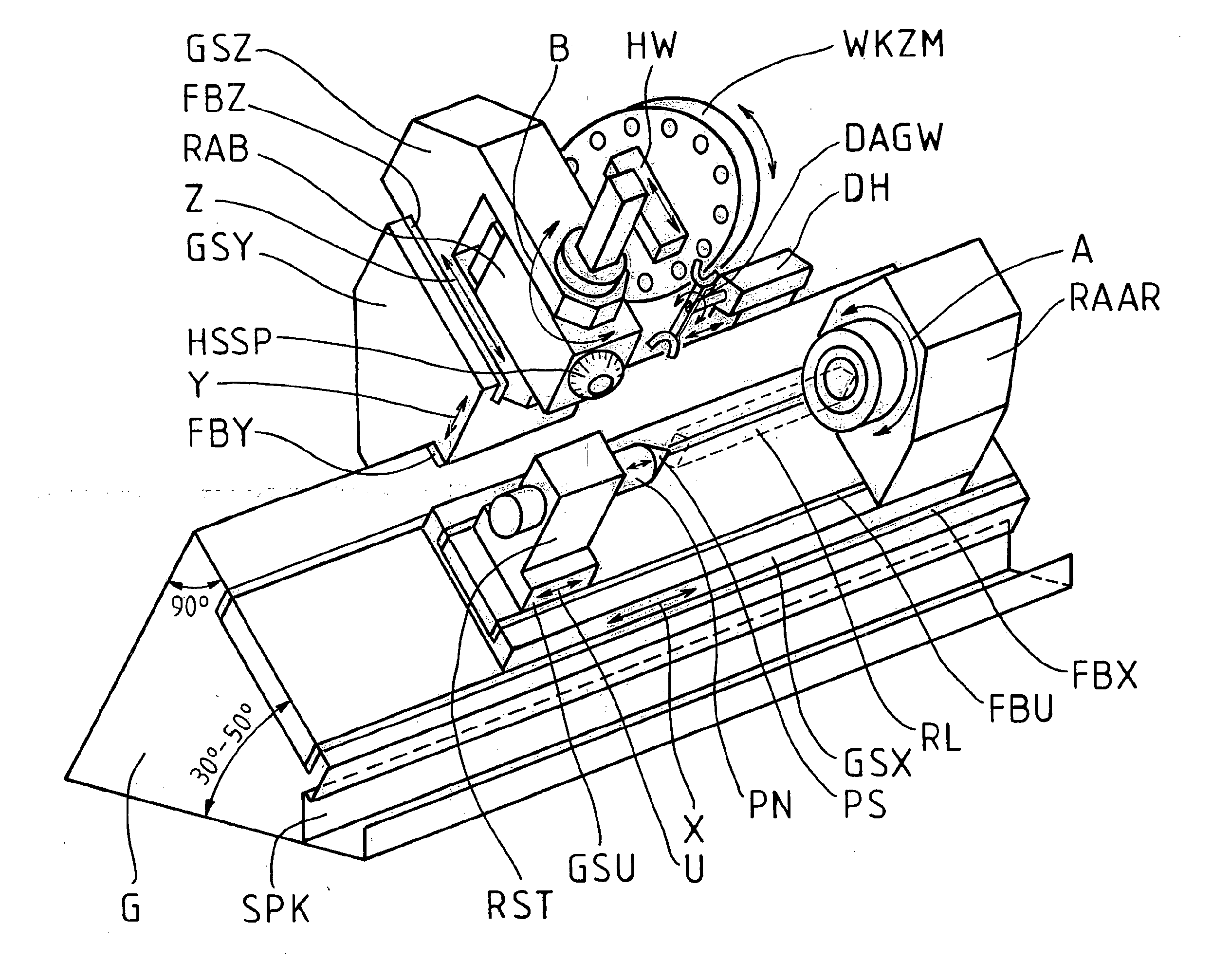
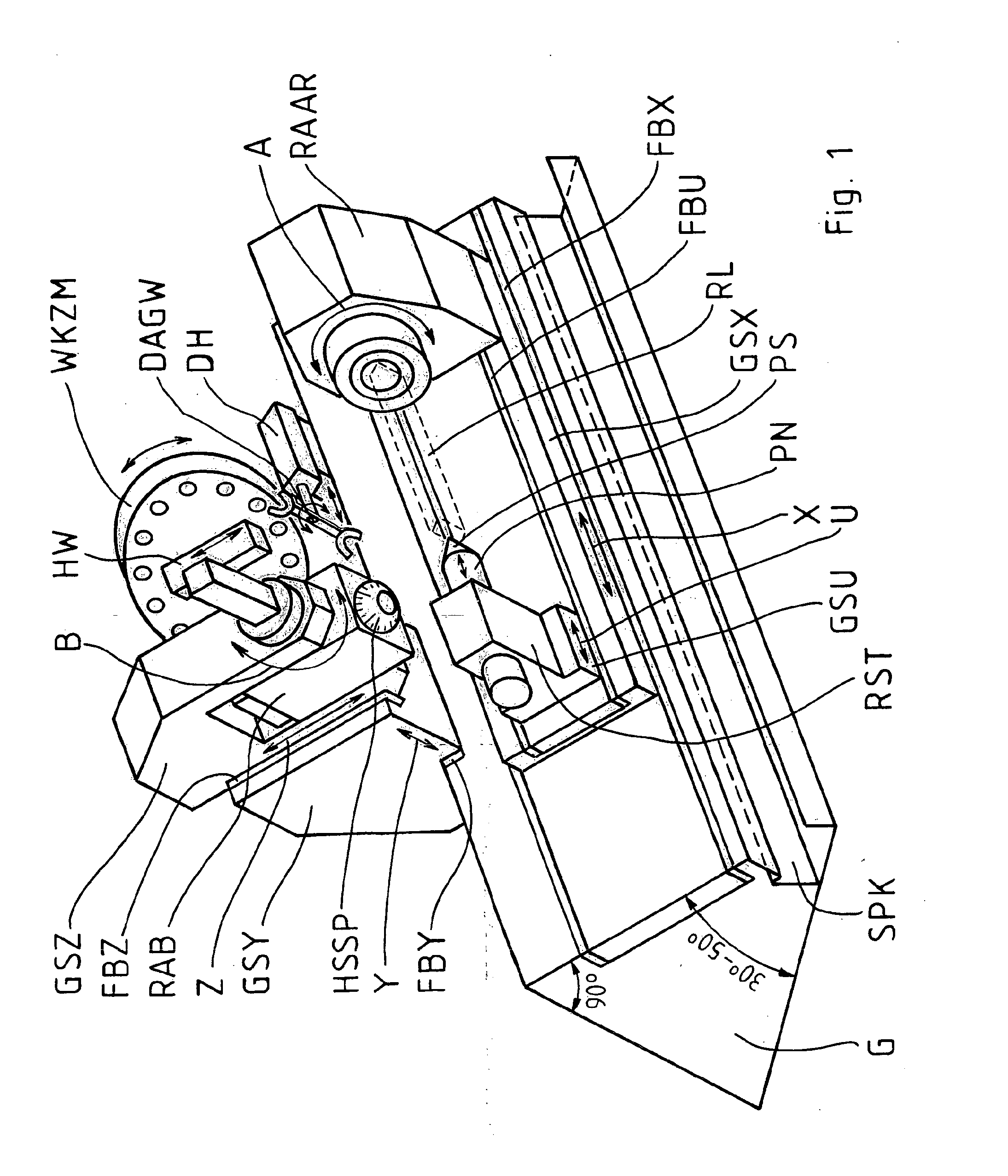
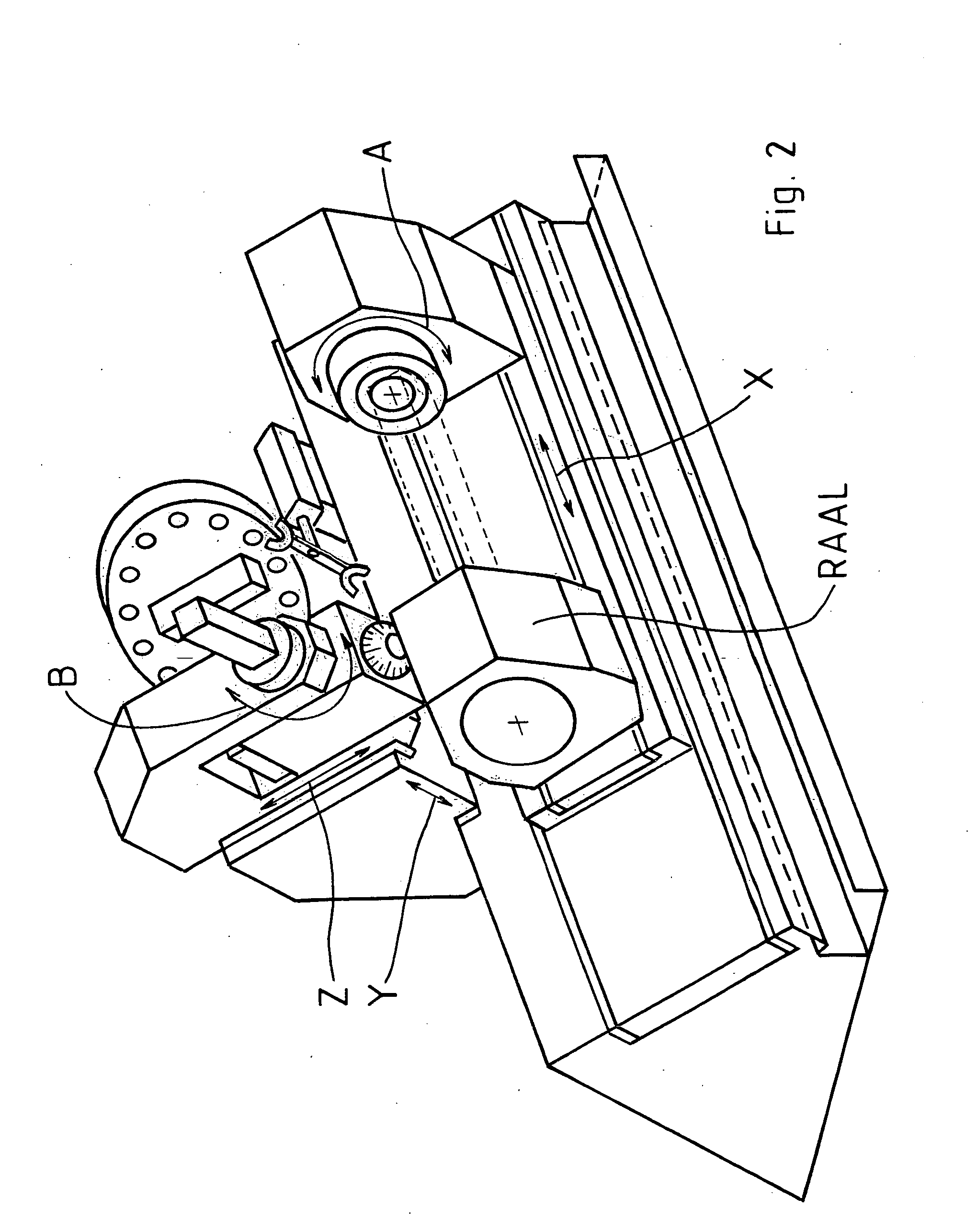
[0041]In the descriptions and drawings, the following designations of the component parts are used:[0042]G Base frame of the machine[0043]FBY Rear Y-bedway[0044]GSY Y-base carriage[0045]FBZ Z-bedway[0046]GSZ Z-base carriage[0047]RAB B-rotation axis[0048]HSSP High frequency milling spindle[0049]FBX Front X-bedway[0050]GSX X-base carriage[0051]RAAR Right A-rotation axis[0052]FBU U-bedway[0053]GSU U-base carriage[0054]RST Tailstock[0055]PN Sleeve—tailstock[0056]PS Sleeve center[0057]WKZM Tool magazine[0058]DAWG Twin-arm tool gripper[0059]DH Automatic traveling system for the twin-arm gripper[0060]DW Tool magazine travel arm[0061]SPK Collecting channel[0062]RAAL Left A-rotation axis[0063]GSXR X-rotation axis carriage[0064]RAC C-rotation axis[0065]WE Winder[0066]RAD D-rotation axis[0067]RSS D-rotation axis clamping medium

[0068]The illustrated machining tool, for example a high-speed rotary miller (HSTM), is built on the basic concept of the machine, that work pieces with a swing of up to...


PUM

PropertyMeasurementUnit
Dimensionaaaaaaaaaa
Circumferenceaaaaaaaaaa

Abstract

In order to carry out complete machining of a blank on a machine tool, such as, for example, a rotary miller, the blank is held in at least one clamp during a machining step. All the functional surfaces of the workpiece (circumference and both end faces of the blank) are brought into the final required form corresponding to final use by the machine tool, in particular, the rotary miller. The blank is a blank made from metal or a ceramic material, of cylindrical, square, or polyhedral cross-section, in particular, a rectangular block or any shaped cast or forged blank. The required form is the head of a turbine blade, the blade region of the turbine blade, and the root of the turbine blade, wherein the functional surfaces of the head and root are prepared during a clamped phase on the machine tool.

Description

BACKGROUND AND SUMMARY[0001]The present invention concerns a method for completely machining blanks or semi-finished work pieces with a machine tool such as a rotary miller (HSTM), components completely machined in their three-dimensional form, as well as a machine tool such as a rotary miller, for carrying out said method.[0002]In the field of turbine blade manufacturing, these items are usually manufactured in multiple stages on multiple different machines. This means that a blank, usually a square or cylindrical rod, must go through the following completion steps:[0003]In the first step, the blank is passed through a line milling machine in the form of a rhombus rod.[0004]In the second step, most of the material is cut out in the actual blade area by a line milling machine. These two work steps take place on 3-axis machines.[0005]In the third step, the turbine blade profile is machined in the blade area by copy milling machines or NC [numerically controlled] milling machines thro...

Claims


Application Information

Patent Timeline
IPC IPC(8): B23Q1/60B23C3/18
CPCB23C3/18B23C2215/44B23Q1/601Y10T29/49336Y10T409/305544Y10T409/303808Y10T29/5109
Inventor HOHN, WOLF-DIETERSCHERER, FRANK
Owner HAMUEL MASCHENBAU
Why Eureka
Try Eureka