Refrigerant compressor

a compressor and refrigerant technology, applied in the direction of positive displacement liquid engines, piston pumps, lighting and heating apparatus, etc., can solve the problems of large oil amount available, risk that the lubrication oil will mix with the refrigerant, and relatively small risk of refrigerant mixing, etc., to achieve low cost, high oil pressure, and simple design

Inactive Publication Date: 2010-04-15
DANFOSS AS
View PDF14 Cites 2 Cited by
  • Summary
  • Abstract
  • Description
  • Claims
  • Application Information

AI Technical Summary

Benefits of technology

[0017]It is preferred that the crank pin is located radially outside an opening of the gas channel at the lower end of the crankshaft. Thus, the crank pin does not hinder the escape of gas from the gas channel. Further, now the crank pin is located so far radially outwards that the oil channel passing through the crank pin has a sufficient radial distance to the crankshaft axis. The larger this distance is, the larger is the centrifugal force acting upon the oil and the larger can the pressures generated in the oil pressure chamber be made.
[0018]Preferably, the oil pump arrangement has a first delivery element, which is submerged in the oil sump and has a smaller diameter at the lower end than at the upper end and is provided with a cover element at the upper end, and a second delivery element with a radial delivery channel connecting an opening in the cover element to the oil channel starting radially further outwards. With such an embodiment, the first delivery element, in the form of a “classical” oil pump, can provide an initial pressure, that is, the first delivery

Problems solved by technology

The oil channel arranged eccentrically to the crankshaft axis causes that a relatively large oil amount is available, also at low speeds o

Method used


Image

  • Refrigerant compressor
  • Refrigerant compressor
  • Refrigerant compressor

Examples


Embodiment Construction

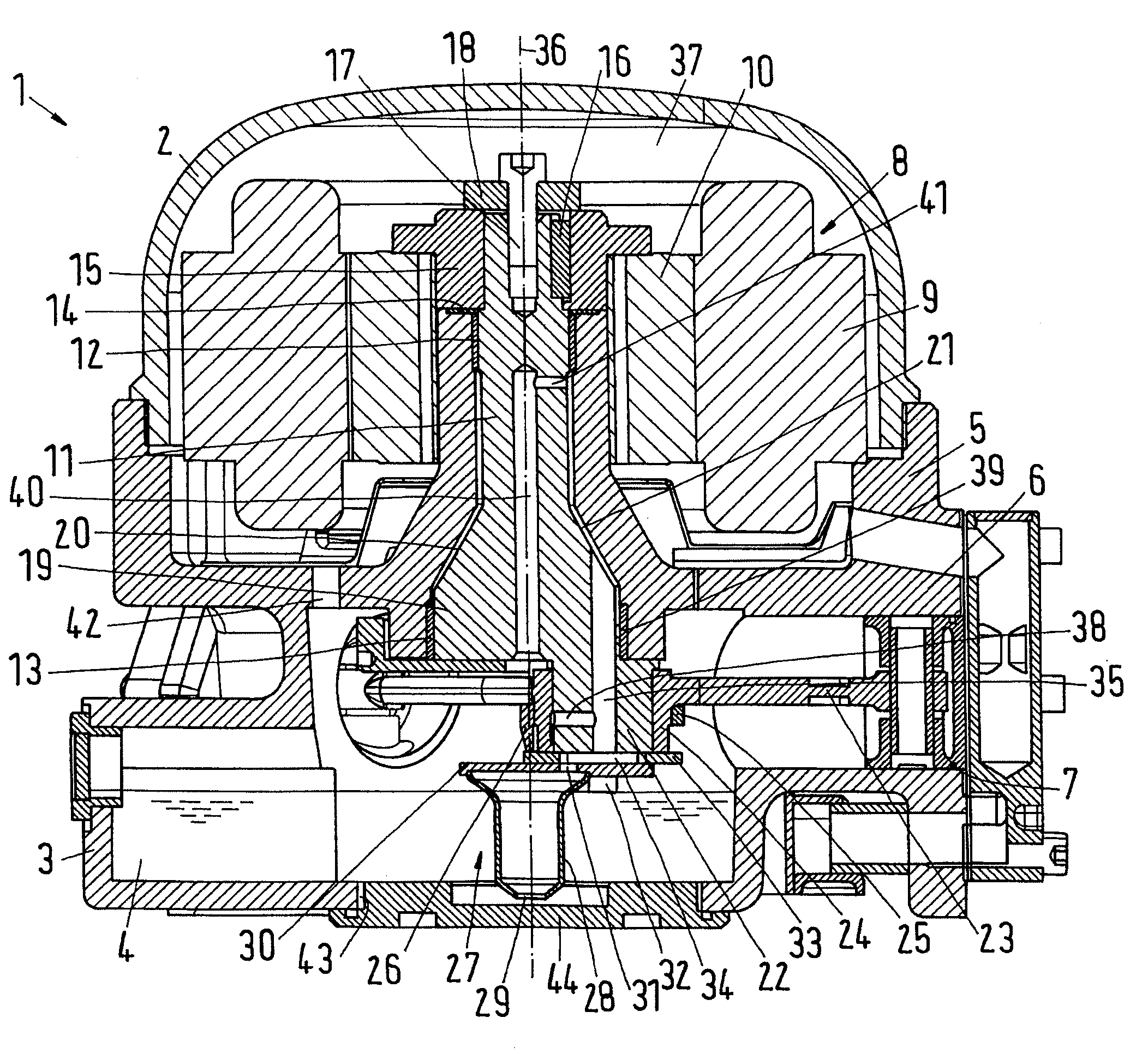
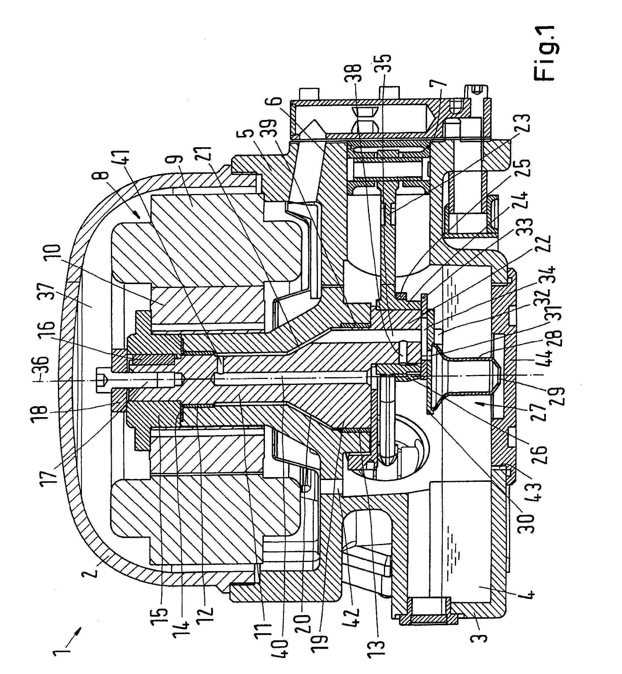
[0027]FIG. 1 shows a semi-hermetic refrigerant compressor 1 with a housing 2, in whose bottom part 3 an oil sump 4 is located. The compressor 1 comprises a compressor block 5, in which several, in the present case three, cylinders 6 are arranged symmetrically and in a star-shape, that is, in the circumferential direction the central axes of the cylinders 6 have a distance of 120°. A piston 7 is arranged in each cylinder 6.

[0028]It is shown that the bottom part 3 of the housing 2 is made in one piece with the compressor block 5. This is advantageous, but not absolutely necessary. A subdivision can be made between the bottom part 3 and the compressor block 5. The compressor block 5 and the bottom part 3 can be made as castings.

[0029]Further, the compressor 1 has an electric motor 8, whose stator 9 is connected to the compressor block 5 in a manner not shown in detail. Further, the motor 8 has a rotor 10. The motor can be a permanent-magnet driven synchronous motor, whose rotor can com...


PUM


Abstract

The invention concerns a refrigerant compressor (1), particularly a semi-hermetic refrigerant compressor, with a housing (2), having in its bottom part (3) an oil sump (4), a compressor block (5) having at least one cylinder (6), in which a piston (7) is arranged, a crankshaft (11), which is supported in the compressor block (5) and in driving connection with the piston (7), and an oil pump arrangement (27), which is at least partly submerged in the oil sump. Also with varying speeds, good oil lubrication must be ensured. For this purpose, the crankshaft (11) has at its lower end a diameter extension (19), through which an oil channel (35) extends eccentrically to the crankshaft axis (36), said channel (35) connecting the oil pump arrangement (27) to a closed oil pressure chamber (21) between the crankshaft (11) and the compressor block (5), said chamber (21) being connected to the inside (37) of the housing (2) via a vent path (40, 41).

Description

CROSS REFERENCE TO RELATED APPLICATION[0001]Applicant hereby claims foreign priority benefits under U.S.C. §119 from German Patent Application No. 10 2008 025 320.0 filed on May 27, 2008, the contents of which are incorporated by reference herein.FIELD OF THE INVENTION[0002]The invention concerns a refrigerant compressor, particularly a semi-hermetic refrigerant compressor with a housing, having in its bottom part an oil sump, a compressor block having at least one cylinder, in which a piston is arranged, a crankshaft, which is supported in the compressor block and in driving connection with the piston, and an oil pump arrangement, which is at least partly submerged in the oil sump.BACKGROUND OF THE INVENTION[0003]Such a refrigerant compressor is, for example, known from GB 1,122,348. This refrigerant compressor has in one embodiment three cylinders arranged in a star-shape. The pistons arranged in the cylinders are driven to a reciprocating movement by the crankshaft via a common c...

Claims


Application Information

Patent Timeline
IPC IPC(8): F04B39/02F04B27/04
CPCF04B39/0246F25B31/002F25B1/02F04B39/0261
Inventor SUSS, JURGENJEPSEN, CHRISTIAN
Owner DANFOSS AS
Why Eureka
Try Eureka