
Wood fibre based panels with a thin surface layer

a technology of wood fibre based building panels and surface layers, which is applied in the direction of adhesive types, lamination, decorative arts, etc., can solve the problems of inferior impact resistance and sound, limited depth of embossing, and high cost of methods, so as to increase impact resistance and market shar

Active Publication Date: 2010-04-15
VÄLINGE INNOVATION AB
View PDF72 Cites 169 Cited by
  • Summary
  • Abstract
  • Description
  • Claims
  • Application Information

AI Technical Summary

Benefits of technology

[0021]Wood fibre based floorings with thin surface layers similar to laminate and wood veneer floorings could capture a considerably larger market share if deep embossing and increased impact resistance could be reached in combination with a cost effective production method.
[0022]An overall objective of an embodiment of the present invention is to provide a building panel, preferably a floor panel, with a thin surface layer, which has a more attractive surface design and / or better surface properties and / or cost structure than present known floorings with conventional thin surface layers.
[0023]A specific objective of an embodiment of the invention is to provide a method to produce a floor panel with new attractive design features such as deep embossing which preferably could be combined with high impact and wear resistance, improved sound properties and cost effective production.

Problems solved by technology

The major disadvantage is that properties related to deep surface structures, impact resistance and sound are inferior to the real products that they aim to copy.
The depth of the embossing is limited by the paper that could be damaged when the embossing is made with sharp edges or to a depth, which exceeds a few tenths of a millimetre.
Embossed surfaces similar to a rough stone surface or a hand scraped wood surface or deep grooves that could be used to make bevels in a panel are not possible to make with the present pressing technology and with a reasonable cost structure maintaining the present technical properties and design.
Such methods are expensive due to the fact that the pressure and pressing time must be increased from the normal level of 300-400 N / cm2 to about 800 N / cm2 and additional expensive material such as a core paper must be included in the panel under the decorative paper.
Usually even the balancing layer has to be made thicker and this will increase the cost further.
This gives a low impact resistance and it is difficult to form high quality locking systems in such soft materials.
Sufficient impact resistance can only be reached if thin surface layers are applied on a rather thick core with a high density.
This means that the core material will be expensive and generally a board quality must be used that has better properties than what is needed for the overall stability of the panel and the strength of the locking system.

Method used


Image

  • Wood fibre based panels with a thin surface layer
  • Wood fibre based panels with a thin surface layer
  • Wood fibre based panels with a thin surface layer

Examples


Embodiment Construction

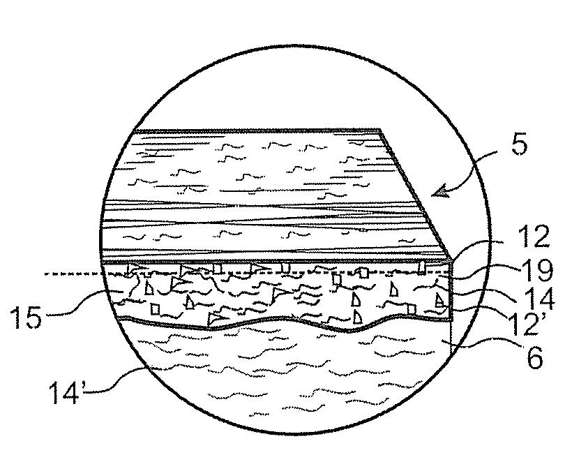
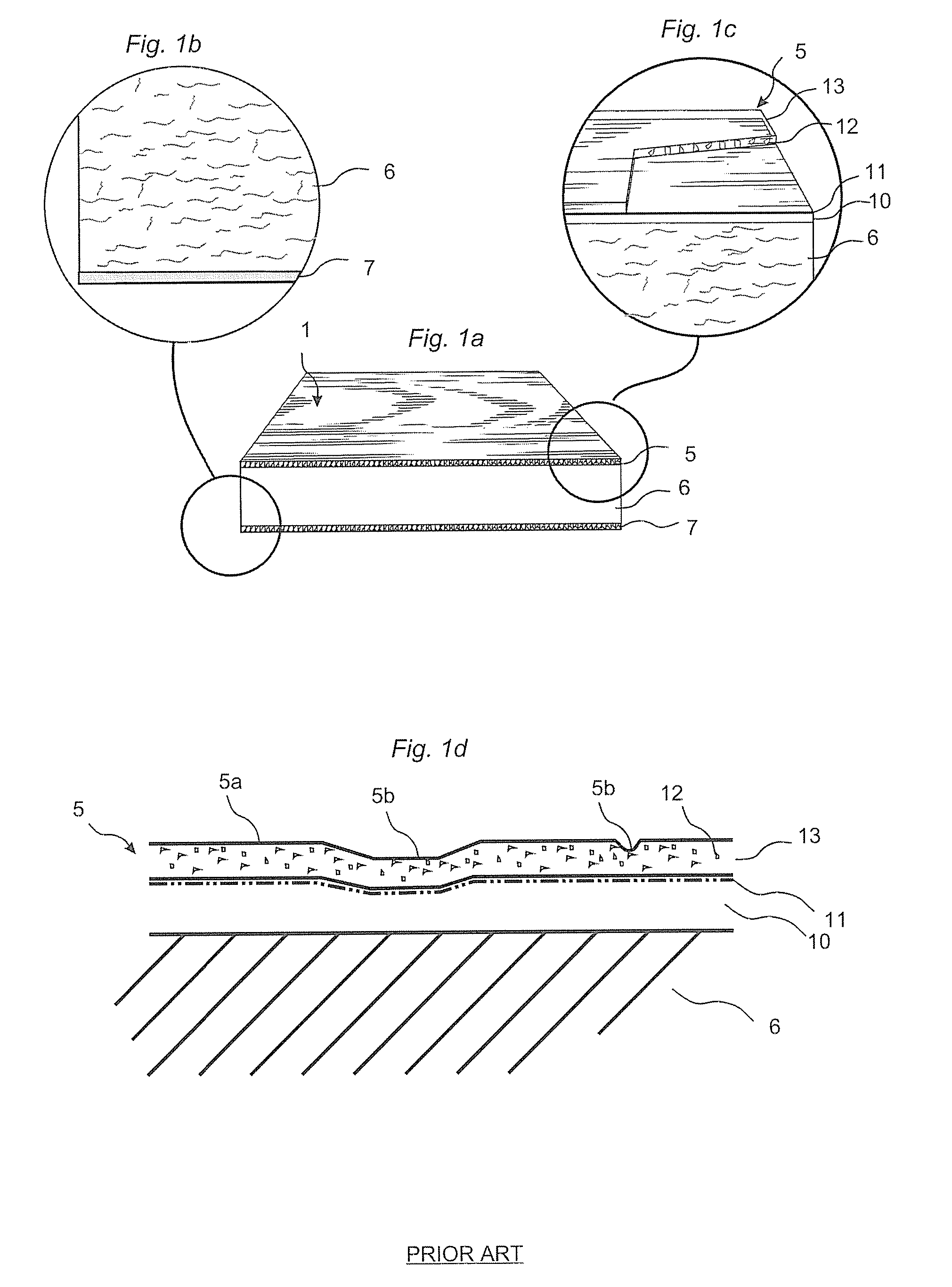
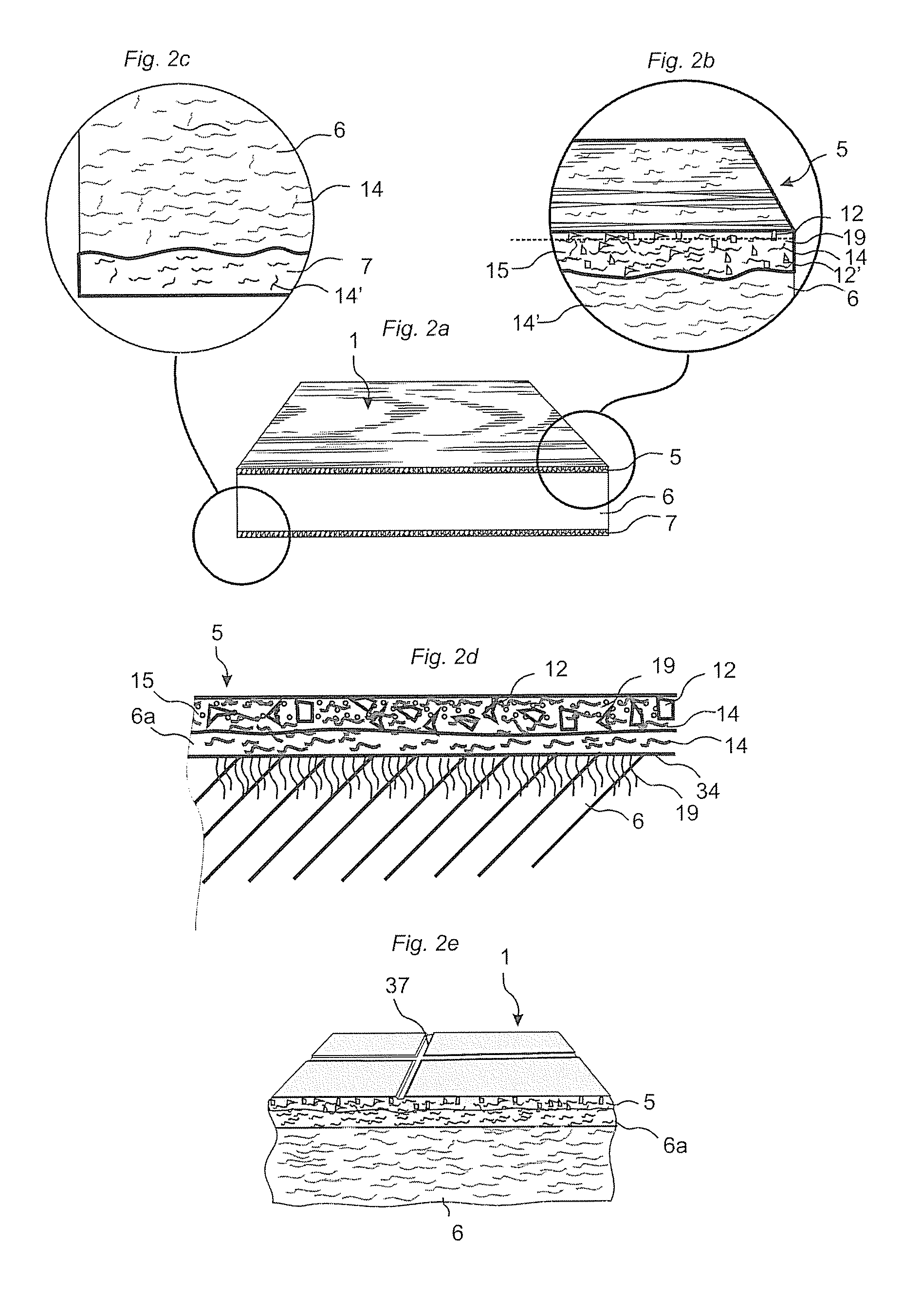
[0063]FIG. 1a shows a laminated floor panel 1 according to known technology comprising a surface layer 5, a core 6 and a balancing layer 7. FIG. 1c shows the surface layer 5. It has an upper wear layer 13 of a transparent material with great wearing strength. Such a wear layer comprises generally a transparent paper impregnated with melamine resin and with aluminum oxide particles 12 added. A decorative layer 10 comprising paper with a printed pattern 11 is impregnated with melamine resin and placed under this transparent wear layer 13. The wear layer 13 and the decorative layer 10 are laminated to the core, generally a fibre based core such as HDF, under pressure and heat to an about 0.2 mm thick surface layer 5. FIG. 1b shows the balancing layer 7 that generally also is a melamine-impregnated paper. This balancing layer keeps the floor panel flat when humidity varies over time. The transparent wear layer is generally 0.05-0.10 mm thick.

[0064]FIG. 1d shows a laminate flooring with ...


PUM

PropertyMeasurementUnit
angleaaaaaaaaaa
thicknessaaaaaaaaaa
thickaaaaaaaaaa

Abstract

Building panels with a thin and embossed surface layer and a sub layer between a surface layer and a core.

Description

CROSS REFERENCE TO RELATED APPLICATIONS[0001]The present application claims priority to U.S. Ser. No. 61 / 042,938, filed on 7 Apr. 2008, and U.S. Ser. No. 12 / 270,257, filed on 13 Nov. 2008, both of which are incorporated herein in their entirety.TECHNICAL FIELD[0002]The invention generally relates but is not limited to the field of wood fibre based building panels with a thin surface layer, preferably floor panels. The invention relates but is not limited to building panels with such surface layer and to equipment and methods to produce such panels.FIELD OF APPLICATION OF THE INVENTION[0003]The present invention is particularly suitable for use in floating floors, which are formed of floor panels with a wood fibre core and a thin decorative wear resistant surface. The following description of prior-art technique, problems of known systems and objects and features of the invention will therefore, as a non-restrictive example, be aimed above all at this field of application and in part...

Claims


Application Information

Patent Timeline
Patent Type & Authority Applications(United States)
IPC IPC(8): B32B21/04B32B3/02B32B38/10C09J161/28B05C1/00
CPCB32B21/02Y10T156/1039B32B37/1027B32B37/153B32B37/156B32B37/24B32B38/06B32B38/145B32B2307/554B32B2307/718B32B2309/02B32B2309/04B32B2309/105B32B2309/12B32B2471/00B32B2607/00E04C2/16E04C2/246E04F15/02E04F15/181E04F2201/0138E04F2201/0153E04F2201/0541E04F2290/042Y10T156/1002Y10T428/24612B32B27/04Y10T428/31982Y10T428/31989B27N3/06B27M1/08B27M3/04E04C2/30E04C2002/005
Inventor PERVAN, DARKOJACOBSSON, JANLINDGREN, KENTZIEGLER, GORANHAKANSSON, NICLASBOUCKE, EDDY
Owner VÄLINGE INNOVATION AB
Learn More