Multi-dimensional volterra series transmitter linearization

a transmitter and multi-dimensional technology, applied in the field of distortion compensation of radio transmitters, can solve the problems of degrading link capacity and/or cell coverage, introducing significant distortion, and reducing the linearization of so as to reduce distortion in amplified analog output signals

Inactive Publication Date: 2010-04-15
MALIKIE INNOVATIONS LTD
View PDF13 Cites 15 Cited by
  • Summary
  • Abstract
  • Description
  • Claims
  • Application Information

AI Technical Summary

Benefits of technology

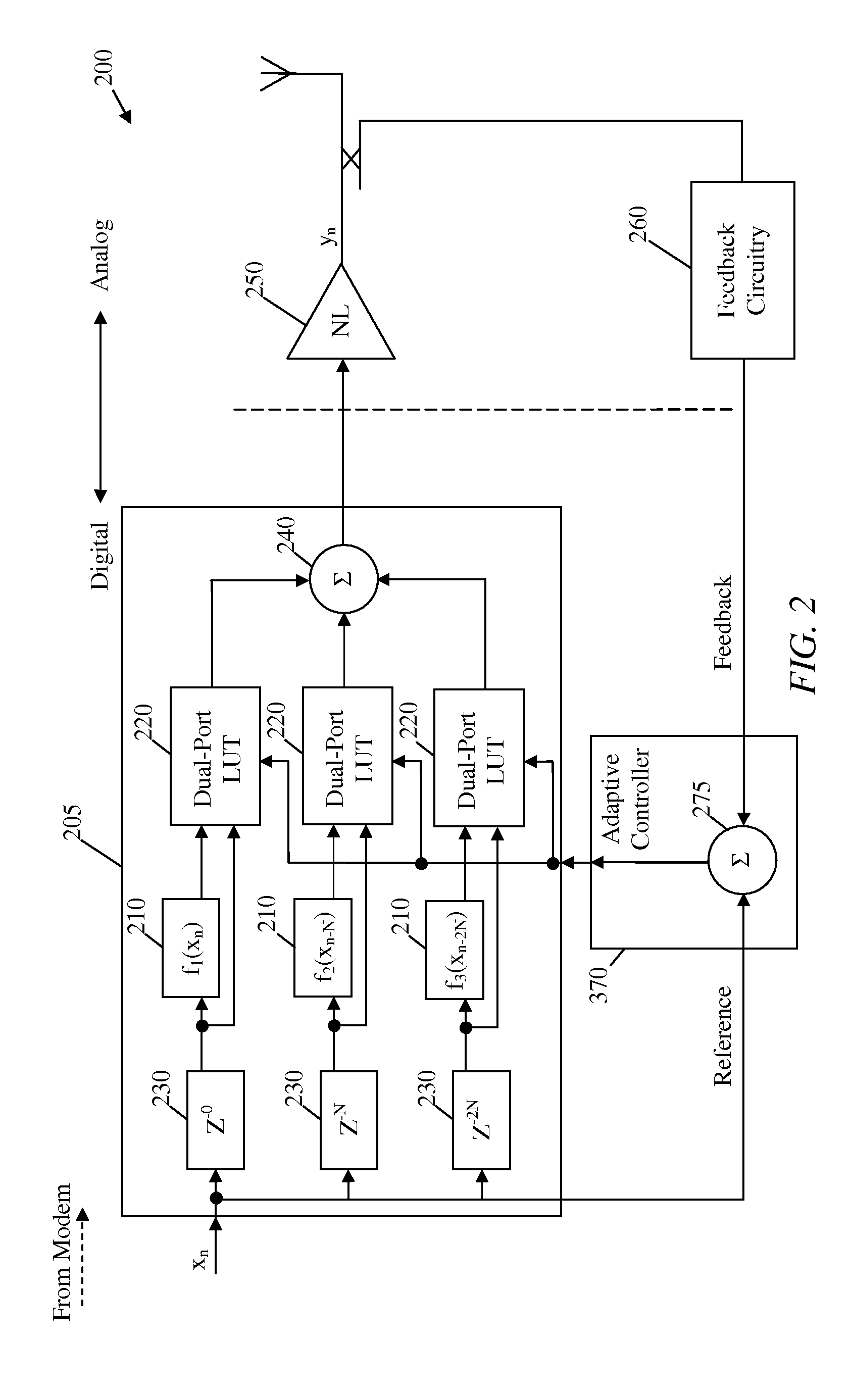
[0009]In yet another embodiment, the disclosure includes a signal distortion compensation method. The signal distortion compensation method comprises converting a digital input signal into an analog output signal; amplifying the analog output signal; receiving a digital feedback signal from the amplified analog output signal; and reducing distortion in the amplified analog output signal using the digital feedback signal based on a plurality of convolved Volterra-series based models using a plurality of corresponding digital reference signals, a plurality of alternative Volterra-series series based models using a single shared digital reference signal, or both.

Problems solved by technology

To support such signaling formats, the PAs can be combined with high cost peak-power reduction (PPR) techniques, which also yields some drawbacks or inefficiencies.
For example, supporting such signaling formats requires increased power back-off, application of strong PPR techniques, or both, which results in degrading the link capacity and / or cell coverage.
However, the advanced PAs can also introduce significant distortions, including nonlinear responses with strong undesired memory effects and transients, such as time-varying behaviors.
However, the digital pre-distortion linearizers require more complex modeling and more resources, which may be difficult to implement.
For instance, undesired numerical effects, associated with the complexity of implementation, can impair or limit the use of adaptive or more flexible models, which in turn limits the overall performance of the transmission system.

Method used


Image

  • Multi-dimensional volterra series transmitter linearization
  • Multi-dimensional volterra series transmitter linearization
  • Multi-dimensional volterra series transmitter linearization

Examples


Embodiment Construction

[0022]It should be understood at the outset that although an exemplary implementation of one embodiment of the present disclosure is illustrated below, the present system may be implemented using any number of techniques, whether currently known or in existence. The present disclosure should in no way be limited to the exemplary implementations, drawings, and techniques illustrated below, including the exemplary design and implementation illustrated and described herein, but may be modified within the scope of the appended claims along with their full scope of equivalents.

[0023]Disclosed herein is a signal transmission system and method using a plurality of Volterra Engine (VE) linearizers coupled to a PA in a transmission system, which may provide improved linearization efficiency and distortion compensation. Specifically, the VE linearizers may be combined in an optimized series architecture, parallel architecture, or combined architecture, where each VE linearizer may be used to ...


PUM


Abstract

A radio transmission system comprising a plurality of Volterra Engine (VE) linearizers; a power amplifier (PA) coupled to the VE linearizers; a feedback circuitry coupled to the VE linearizers and the PA; and at least one adaptive controller coupled to the feedback circuitry, wherein each VE linearizer is coupled to at least another VE linearizer in series, in parallel, or both, and is configured to compensate for at least one distortion aspect of an output signal from the PA.

Description

CROSS-REFERENCE TO RELATED APPLICATIONS[0001]Not Applicable.STATEMENT REGARDING FEDERALLY SPONSORED RESEARCH OR DEVELOPMENT[0002]Not applicable.REFERENCE TO A MICROFICHE APPENDIX[0003]Not applicable.FIELD OF THE INVENTION[0004]The present invention relates generally to distortion compensation in radio transmitters and, more particularly, to a system and method for improving amplified signal linearization.BACKGROUND OF THE INVENTION[0005]In wireless communications, signals are forwarded using transmission and receiving systems, such as radio based transmitters and receivers. Signal transmission systems may include power amplifiers (PAs), linearizers that compensate for signal distortions in the transmission systems, antennas, and other signal processing components. Modem wireless communications standards, such as 4G cellular standards, require special signaling formats or modulations, which exhibit higher and rapidly varying peak to average ratios (PARs), such as Orthogonal frequency...

Claims


Application Information

Patent Timeline
Patent Type & Authority Applications(United States)
IPC IPC(8): H04B1/04H03F1/26
CPCH03F1/3247H03F1/3258H03F1/3294H03F3/19H04L27/368H03F2200/336H03F2200/451H03F2201/3224H03F2201/3233H03F3/24H04B1/04
Inventor VAN ZELM, JOHN-PETERRASHEV, PETERHOLT, JOHN
Owner MALIKIE INNOVATIONS LTD
Why Eureka
Try Eureka