Pneumatic transport delivery control

US20100094451A1Active Publication Date: 2010-04-15TRANSLOGIC

Image

  • Pneumatic transport delivery control
  • Pneumatic transport delivery control
  • Pneumatic transport delivery control

Examples


Embodiment Construction

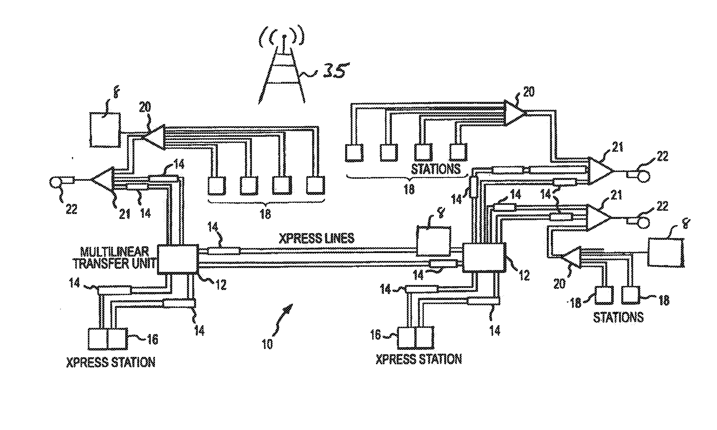
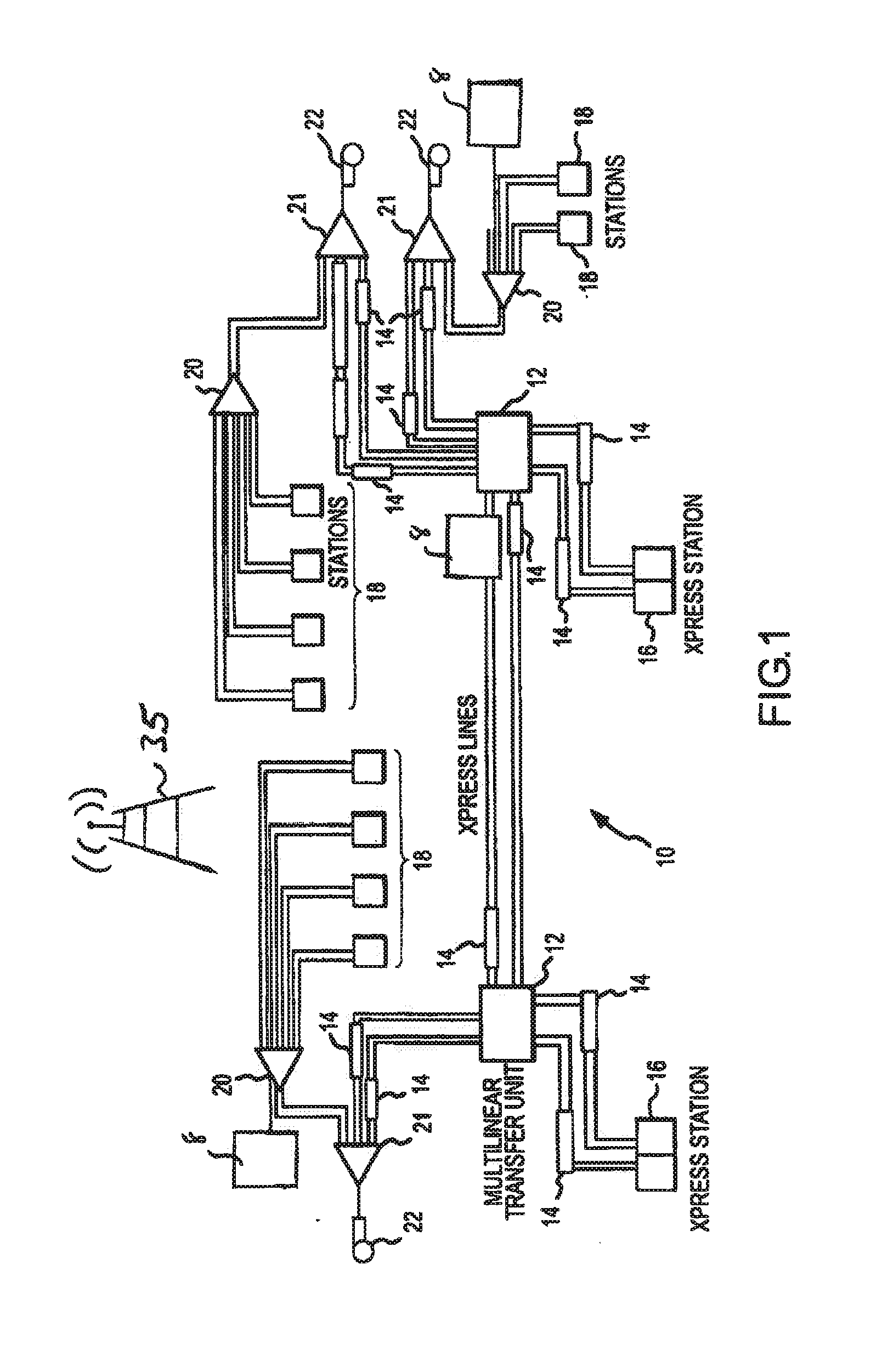
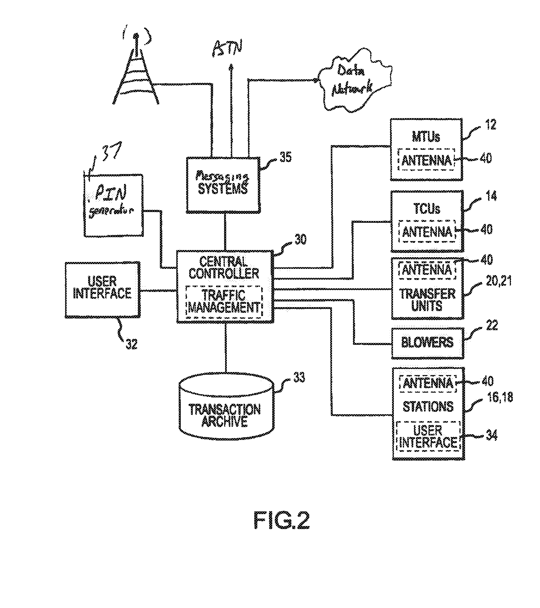
[0034]Reference will now be made to the accompanying drawings, which at least assist in illustrating the various pertinent features of the present invention. In this regard, the following description is presented for purposes of illustration and description. Furthermore, the description is not intended to limit the invention to the form disclosed herein. Consequently, variations and modifications commensurate with the following teachings, and skill and knowledge of the relevant art, are within the scope of the present invention.

[0035]Overview

[0036]Disclosed herein are various systems and methods (hereafter delivery systems) that allow for, inter alia, improving the controlled delivery of a specified transaction and its associated carrier to a specified recipient. The delivery systems create a verifiable chain-of-custody for the specific transaction and carrier. Further, the delivery systems allow a sender and recipient to perform asynchronous activity. That is, the delivery systems ...


PUM


Abstract

The presented inventions seek to create a verifiable and closed loop chain-of-custody for a specific transaction in a pneumatic tube transport system while allowing a sender and recipient to perform asynchronous activity. That is, one aspect the presented inventions allows a sender to securely send a carrier to a desired recipient while allowing the desired recipient to receive the secured carrier at a convenient time and / or location without tying up system resources. Another aspect improves the physical barriers between high value payloads and the unintended recipients. This is done in part by introducing randomness into the carrier delivery process such that no member of the general public or facility staff knows the location and / or delivery time of a secured carrier without having access to specific database records indicating the current location and / or delivery status of the secured carrier.

Description

CROSS REFERENCE TO RELATED APPLICATION[0001]This application claims the benefit of the filing date of U.S. Provisional Application No. 61 / 104,162, entitled ā€œPneumatic Transport Delivery Controlā€ having a filing date of Oct. 9, 2009, the entire contents of which are incorporated herein by reference.FIELD OF INVENTION[0002]The presented inventions relate generally to the field of pneumatic tube carrier systems. More particularly, the presented inventions relate to systems and methods for and controlling and confirming the delivery of pneumatic carriers to intended recipients.BACKGROUND OF THE INVENTION[0003]The fundamental processing means and methods for pneumatic tube systems are well known. Their basic function is transfer of physical packets (ā€œcarriersā€) among a plurality of nodes or terminals (ā€œstationsā€). The stations are physically interconnected by the use of pneumatic tubes / pipes, various types of switches (ā€œtransfer unitsā€, ā€œmulti-linear transfer unitsā€), and queuing and acc...

Claims


Application Information

Patent Timeline
15 Apr 2010
Publication
US20100094451A1
IPC
G06F7/00
CPC
G06Q10/08; B65G51/44
Inventors
HOGANSON, KENNETH MICHAEL; KENNEDY, JOHN ALAN