
Low pressure recovery process for acceleration of in-situ bitumen recovery

a recovery process and low pressure technology, applied in the field of recovery processes of heavy oil or bitumen, can solve the problems of substantial steam loss to the thief zone, affecting the overall rate of recovery, etc., and achieve the effect of encouraging lateral fluid communication and improving oil production

Inactive Publication Date: 2010-04-22
ATHABASCA OIL CORPORATION
View PDF10 Cites 31 Cited by
  • Summary
  • Abstract
  • Description
  • Claims
  • Application Information

AI Technical Summary

Benefits of technology

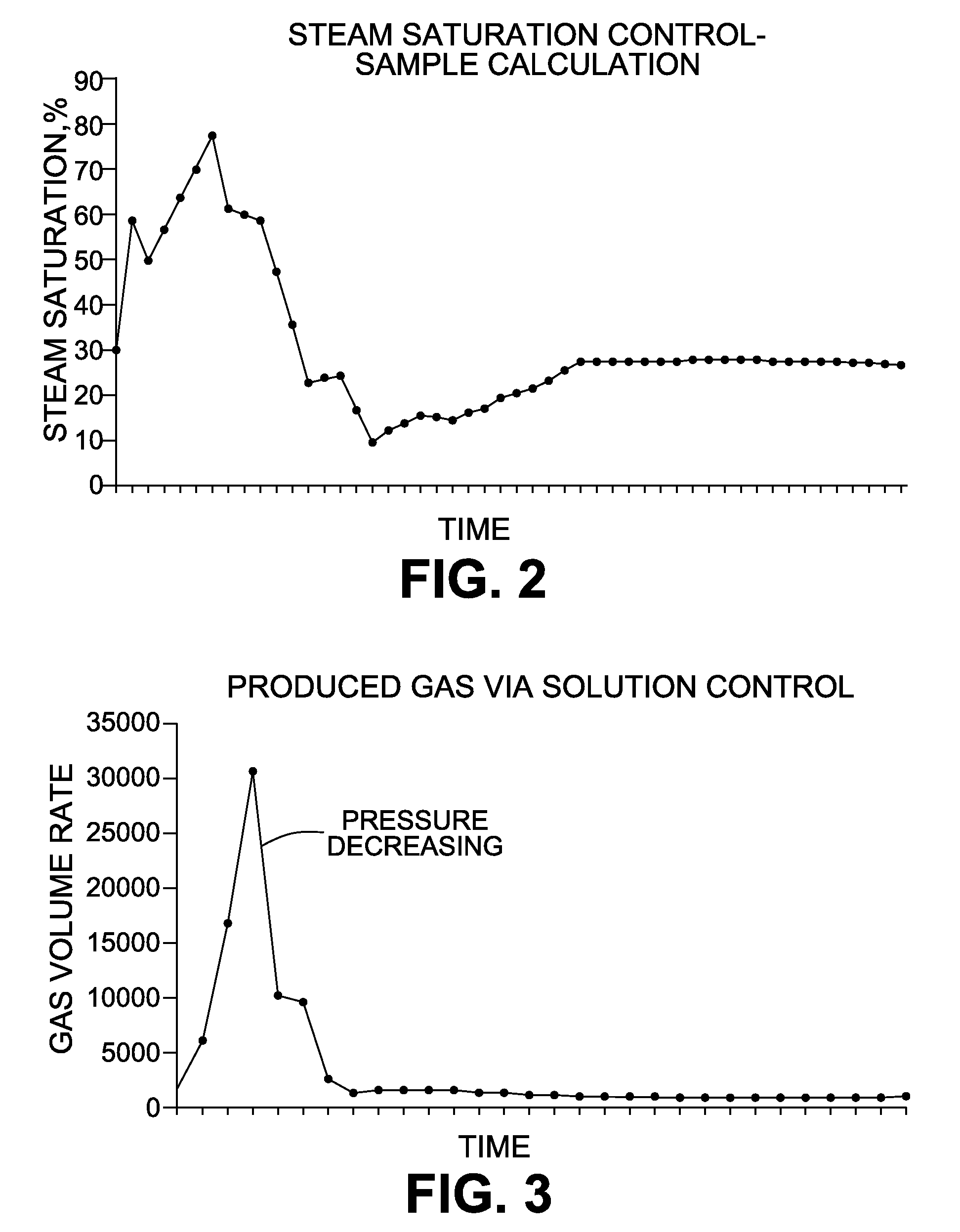
[0013]Controlling the steam saturation in the SAGD zone in such a manner that the vertical rise rate of the steam chamber is controlled to reduce and manage steam loss or breakthrough to low pressure zones, by means of controlled gas co-injection with steam;
[0014]Introducing a lateral drainage (LD) well to control the amount of gas present in the steam chamber and to encourage horizontal rather than vertical migration of the steam, thus taking advantage of the delayed vertical growth and / or breakthrough of steam to the low pressure zone or loss zone in order to obtain a sweep of the bitumen or heavy oil;
[0017]Production of bitumen or heavy oil is thus possible in an accelerated fashion, and in reservoir conditions where the reservoir pressure is low.
[0018]It is an object of the present invention to obviate or mitigate at least one disadvantage of previous methods and processes for bitumen recovery.

Problems solved by technology

In these conditions, steam losses to the thief zone could be substantial, potentially impacting the overall rate of recovery.

Method used


Image

  • Low pressure recovery process for acceleration of in-situ bitumen recovery
  • Low pressure recovery process for acceleration of in-situ bitumen recovery
  • Low pressure recovery process for acceleration of in-situ bitumen recovery

Examples


Embodiment Construction

[0048]Generally, the present invention provides a low pressure recovery process for acceleration of in-situ bitumen recovery.

[0049]The objective of the invention is to accelerate production and increase recovery of bitumen and / or heavy oil from reservoirs in contact with low pressure subterranean zones, due to factors such as regional geology, depleted gas caps or other thief zones, or lack of cap rock. The invention will hereinafter be referred to as the SAGD Triplet Process.

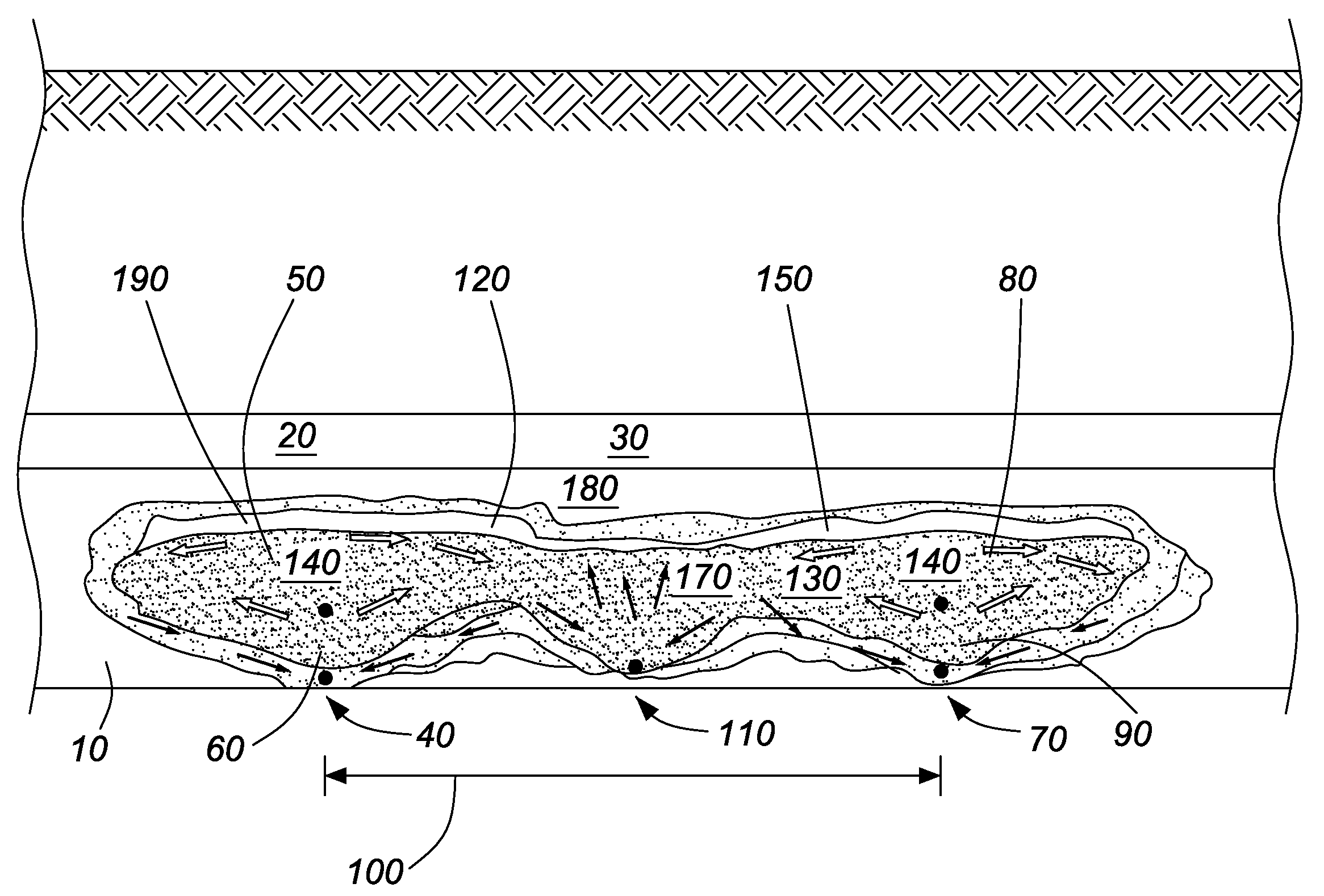
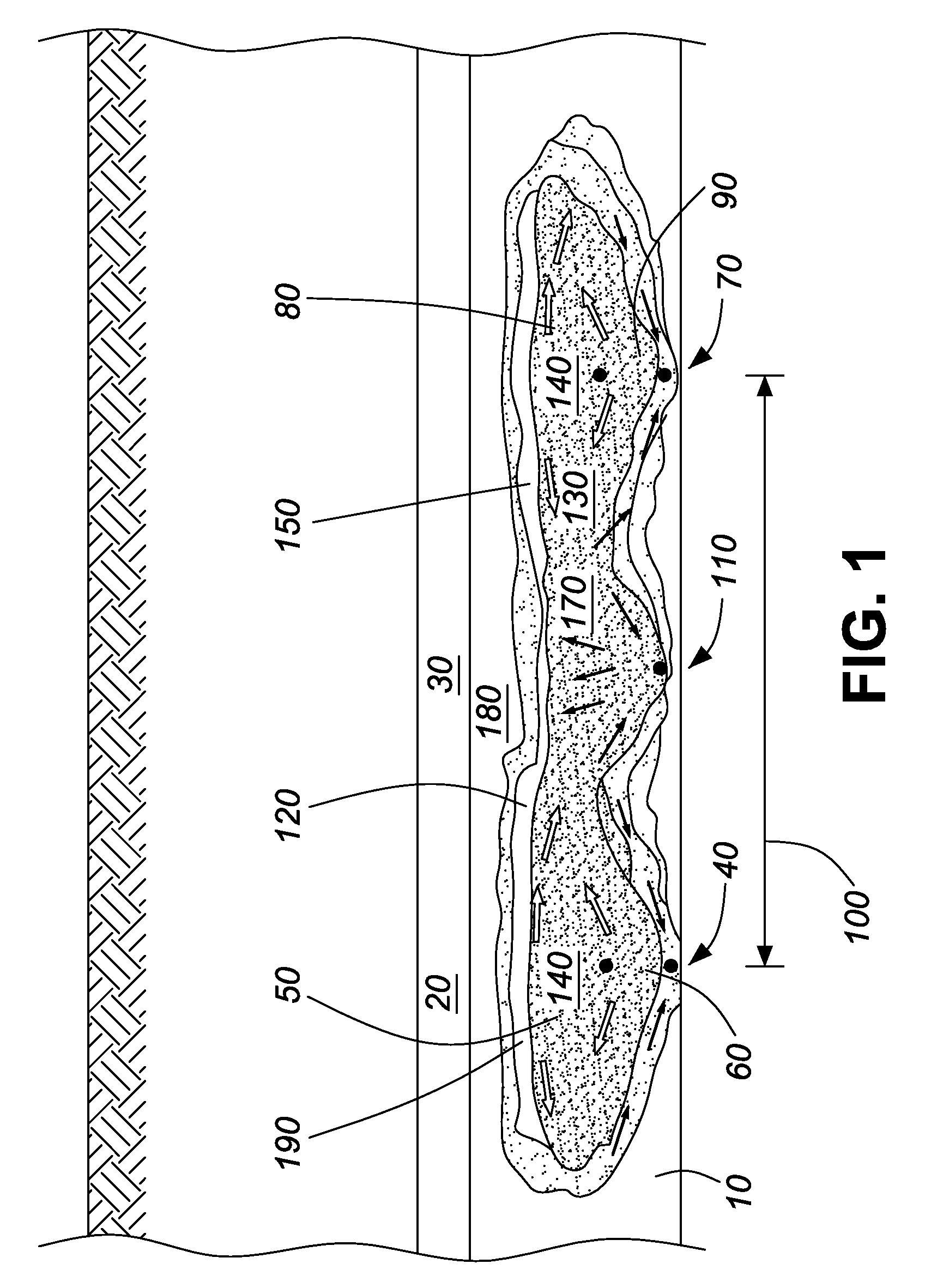
[0050]Referring to FIG. 1, a reservoir of bitumen or heavy oil 10 sits below a low pressure zone or loss zone 20, for example a low pressure (gas) zone 30. A first SAGD well pair 40 having an injection well 50 and a production well 60, and a second SAGD well pair 70 having an injection well 80 and a production well 90 (together the first SAGD well pair 40 and the second SAGD well pair 70 forming adjacent SAGD well pairs 100) are drilled at close lateral spacing of 80 m or greater, as suitable for reservoir cond...


PUM


Abstract

A method for recovery of hydrocarbons from a subterranean reservoir by operating adjacent injector producer well pairs under conditions of steam assisted gravity drainage (SAGD) with a lateral drainage well between and substantially parallel to them; the lateral drainage well is operated under conditions of intermittent steam injection and alternating oil, water and gas production; NCG is co-injected with steam into both the injector wells and the lateral drainage well at selected intervals, and in selected quantities in order to control the steam saturation of the SAGD steam chamber and the rise of the steam chamber, and to encourage lateral fluid communication between the adjacent well pairs and the LD well; controlling gas injection and production in order to control the rise of the steam chamber to improve production of oil; operating the well pairs and the LD well under conditions of a steam chamber pressure that is initially and briefly high to establish a steam chamber, but thereafter may be reduced to as low as 200 kPa; operating this low pressure SAGD in reservoirs that are at low pressure, due to factors such as depleted gas caps, regional geology, lack of cap rock, thief zones, or other low pressure zone or loss zones.

Description

FIELD OF THE INVENTION[0001]The present invention relates generally to recovery processes of heavy oil or bitumen from an underground oil-bearing reservoir by thermal methods. More particularly, the present invention relates to in-situ recovery of bitumen from an underground oil-bearing reservoir where the initial reservoir pressure is lower than what would be expected via hydrostatic pressure gradient due to regional geological effects, depleted gas caps or other thief zones, or lack of overlying cap rock. More particularly, the present invention relates to recovery processes where overlying underground strata are at low pressure due to any one or more of the factors above, the most common example of which is prior gas production.BACKGROUND OF THE INVENTION[0002]A number of patents relate to the recovery of bitumen or heavy oil from underground reservoirs by thermal methods.[0003]Canadian Patent No. 1,130,201 (Butler) teaches a thermal method for recovering highly viscous oil from ...

Claims


Application Information

Patent Timeline
IPC IPC(8): E21B43/243E21B43/24
CPCE21B43/168E21B43/243E21B43/2408
Inventor SULLIVAN, LAURA A.HERON, CAROLINETHIMM, HARALD F.
Owner ATHABASCA OIL CORPORATION
Learn More