Apparatus for transferring energy using power electronics and machine inductance and method of manufacturing same

a technology of power electronics and power electronics, applied in the direction of dc source parallel operation, electric devices, propulsion using engine-driven generators, etc., can solve the problems of adding extra cost and weight to the vehicle, and adding dedicated components

Active Publication Date: 2010-04-22
GENERAL ELECTRIC CO
View PDF11 Cites 106 Cited by
  • Summary
  • Abstract
  • Description
  • Claims
  • Application Information

AI Technical Summary

Problems solved by technology

These additional dedicated components a

Method used


Image

  • Apparatus for transferring energy using power electronics and machine inductance and method of manufacturing same
  • Apparatus for transferring energy using power electronics and machine inductance and method of manufacturing same
  • Apparatus for transferring energy using power electronics and machine inductance and method of manufacturing same

Examples


Embodiment Construction

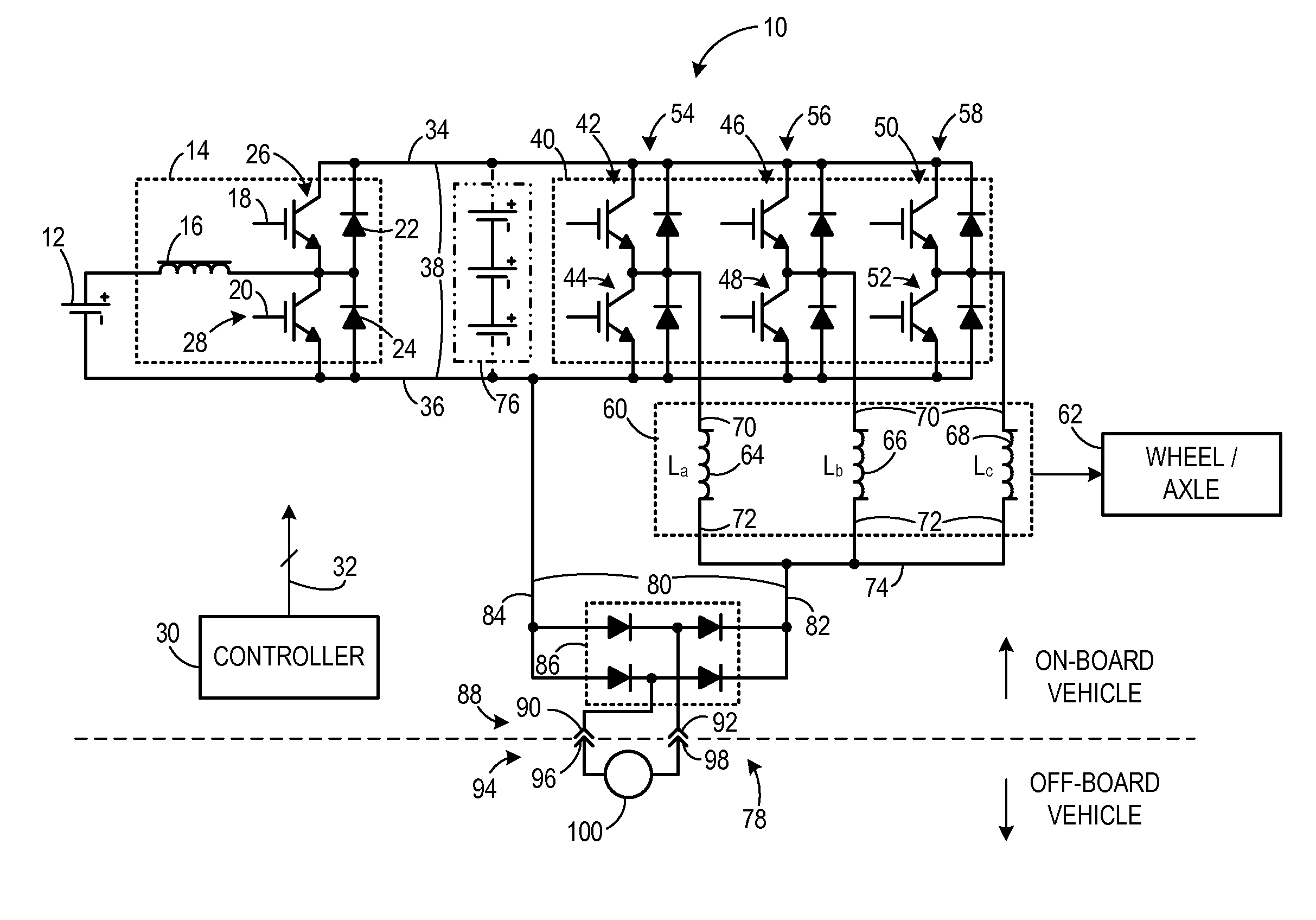
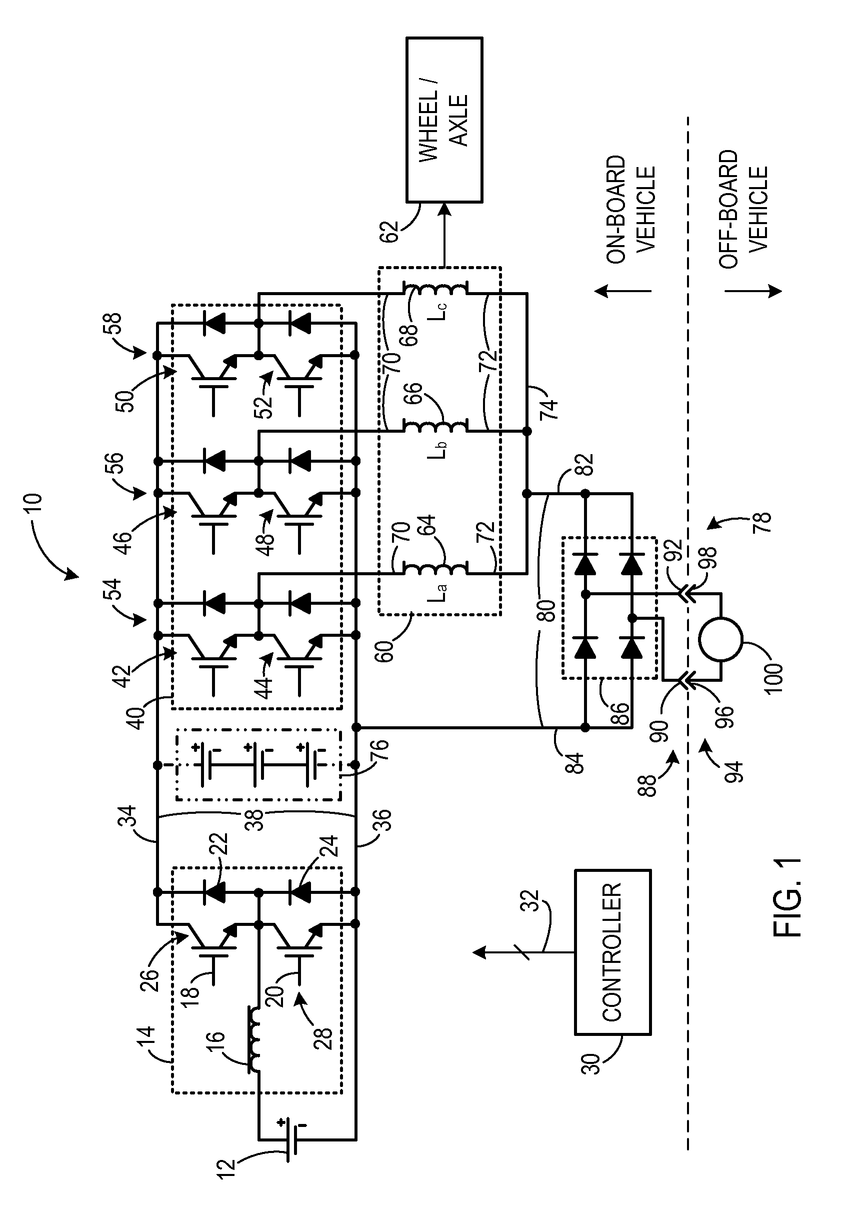
[0018]FIG. 1 is a schematic diagram of a traction system 10 according to an embodiment of the invention. Traction system 10 includes a first energy storage device 12. In one embodiment, first energy storage device 12 is a low-voltage energy storage device and may be a battery, a fuel cell, an ultracapacitor, or the like. First energy storage device 12 is coupled to a bi-directional DC-to-DC voltage converter 14 configured to convert one DC voltage into another DC voltage. Bi-directional DC-to-DC voltage converter 14 includes an inductor 16 coupled to a pair of switches 18, 20 and coupled to a pair of diodes 22, 24. Each switch 18, 20 is coupled to a respective diode 22, 24, and each switch / diode pair forms a respective half phase module 26, 28. Switches 18, 20 are shown, for illustrative purposes, as insulated gate bipolar transistors (IGBTs). However, embodiments of the invention are not limited to IGBTs. Any appropriate electronic switch can be used, such as, for example, metal ox...


PUM

PropertyMeasurementUnit
Electrical inductanceaaaaaaaaaa
Currentaaaaaaaaaa
Electric potential / voltageaaaaaaaaaa

Abstract

A traction inverter circuit includes a first energy storage device configured to output a DC voltage, a first bi-directional DC-to-AC voltage inverter coupled to the first energy storage device, and a first electromechanical device. The first electromechanical device includes a first plurality of conductors coupled to the first bi-directional DC-to-AC voltage inverter, a second plurality of conductors coupled together, and a plurality of windings coupled between the first plurality of conductors and the second plurality of conductors. The traction converter circuit also includes a charge bus comprising a first conductor coupled to the second plurality of conductors of the first electromechanical device, the charge bus configured to transmit a charging current to or receive a charging current from the first electromechanical device to charge the first energy storage device via the first electromechanical device and the first bi-directional DC-to-AC voltage inverter.

Description

BACKGROUND OF THE INVENTION[0001]The invention relates generally to electric drive systems including hybrid and electric vehicles and to stationary drives that are subject to transient or pulsed loads and, more particularly, to transferring energy between an electrical storage device of the vehicle or drive and a power source external to the vehicle.[0002]Hybrid electric vehicles may combine an internal combustion engine and an electric motor powered by an energy storage device, such as a traction battery, to propel the vehicle. Such a combination may increase overall fuel efficiency by enabling the combustion engine and the electric motor to each operate in respective ranges of increased efficiency. Electric motors, for example, may be efficient at accelerating from a standing start, while combustion engines may be efficient during sustained periods of constant engine operation, such as in highway driving. Having an electric motor to boost initial acceleration allows combustion eng...

Claims


Application Information

Patent Timeline
IPC IPC(8): H02M7/79B60L50/15B60L50/16
CPCB60L11/123Y10T29/49108B60L11/1811B60L11/1814B60L11/1816B60L15/007B60L2210/20B60L2210/40B60L2220/54Y02T10/6217Y02T10/641Y02T10/7005Y02T10/7077Y02T10/7094Y02T10/7241Y02T10/725Y02T90/127Y02T90/14H02J7/0052Y10T29/49117B60L11/14Y02T10/7072B60L53/14B60L50/61B60L50/16B60L53/20B60L53/24B60L2210/10Y10S903/907Y02T10/62Y02T10/64Y02T10/72Y02T10/70Y02T10/92B60L55/00B60L50/50B60W10/08B60W20/00H02M7/797H02M3/33584H02J3/322Y02T90/10Y04S10/126H02J7/00Y02T90/12
Inventor KING, ROBERT DEANSTEIGERWALD, ROBERT L.
Owner GENERAL ELECTRIC CO
Why Eureka
Try Eureka