RFID tags

a technology of rfid tags and tags, applied in the field of rfid tags, can solve the problems of low value of tag q, system susceptible to severe degradation, and insufficient communication bandwidth, and achieve the effects of high q operation, fast response, and extended powering rang

Active Publication Date: 2010-04-22
SUREFLAP
View PDF8 Cites 10 Cited by
  • Summary
  • Abstract
  • Description
  • Claims
  • Application Information

AI Technical Summary

Benefits of technology

[0028]The use of feedback and / or a local energy store to assist the tag transitions therefore enables high Q operation and extended range for the powering field, whilst also a fast response for tag to reader communication and / or reader to tag communication. Although the embodiments focus on implementation of these functions with the self-adaptive resonator, they may be equally well applied to a conventional linear resonator of high Q.
[0029]According to another aspect of the invention, the tag locally stores energy from the reader field that is subsequently used to augment the reader field when transitioning between levels in the tag. This may be used to achieve a faster response than simply allowing the antenna to ramp slowly in amplitude in response to the powering field. In this manner a high tag current may be achieved quickly, and this fast change in state allows high levels of power to be derived from the reader field quicker; this is because the energy derived from the reader is directly related to the amplitude and phase of the current in the tag. The store of energy may take place over a number of cycles, or recovered from a single transition from a high amplitude to a low amplitude state. The energy store may be in the form of charge on a capacitor and / or current in an inductor. The tag may include means to reduce the amplitude of transients generated during the energy recovery process.
[0030]According to another aspect of the invention the use of the self-adaptive resonator, possibly in combination with a tuning circuit once the tag is powered, not only improves the tolerance to detuning of the tag but also may allow use of the same tag with multiple frequencies. Examples include a low frequency tag operating at the two common low frequencies of 125 kHz and 134 kHz or an ultra high frequency tag operating over the band 860 MHz to 960 MHz. Here the self-adaptive resonator is able to power up the tag across the range of required frequencies, then operating the same resonator or a conventional resonator with a powered tuning circuit for subsequent communication.

Problems solved by technology

However, two constraints mean that the tag Q is limited to low values of order 10:1) As the tag Q increases the width of the resonance drops proportionally.
This makes the system susceptible to severe degradation due to environmental detuning or variation at manufacture.2) The system is also required to communicate once the tag is powered.
A high tag Q does not give sufficient bandwidth for communication and the amplitude of any load modulation, when registered at the reader, is attenuated.

Method used


Image

  • RFID tags
  • RFID tags
  • RFID tags

Examples


Embodiment Construction

[0063]The following description of a resonant circuit responsive to a wide frequency range is merely exemplary in nature and is in no way intended to limit the invention or its applications or uses. Those skilled in the art will recognise that in addition to the field of RED it may equally well be applied to any area requiring the generation or detection of modulation with a resonant antenna.

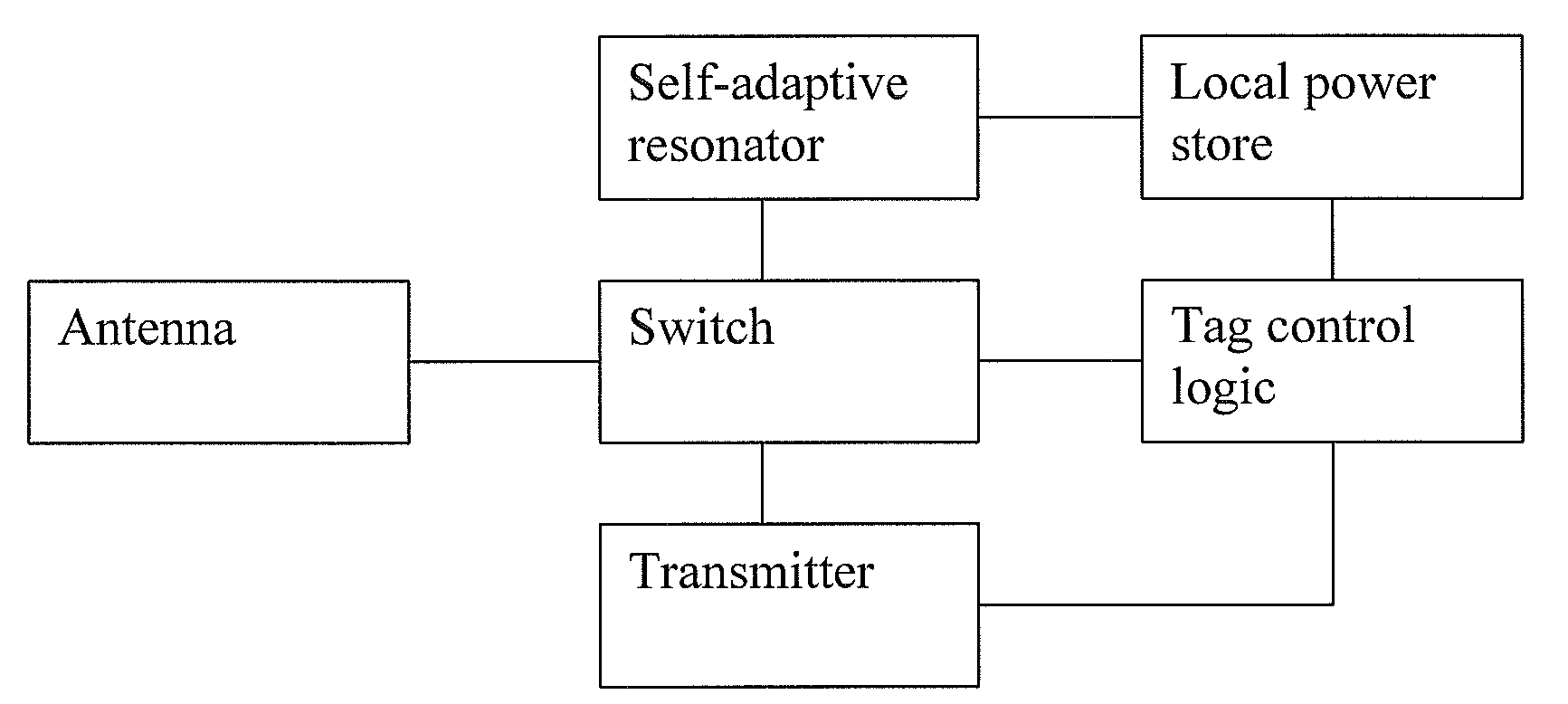
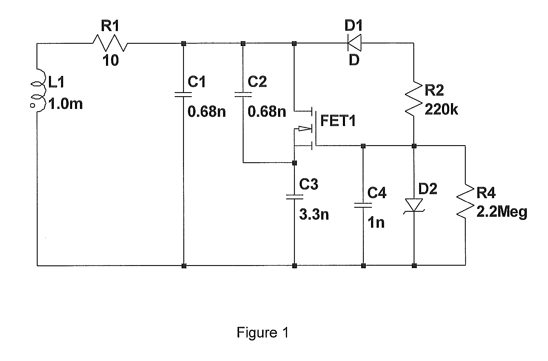
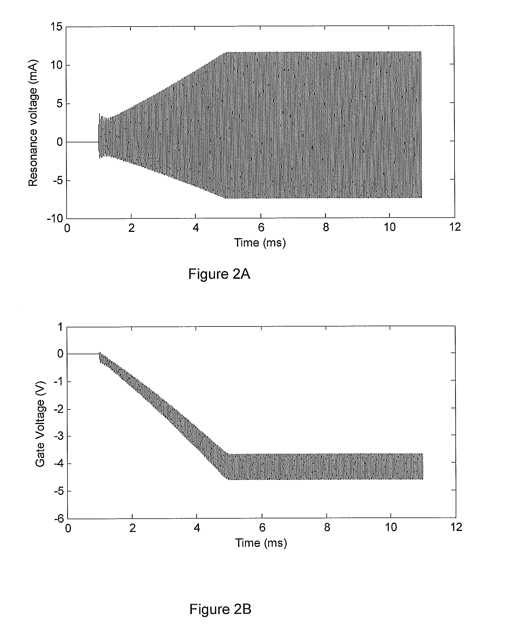
[0064]FIG. 1 shows a schematic of the self-adaptive resonator applied to a tag. The resonator is based on an antenna with 1 mH inductance and 10 Ω resistance, giving a Q of approximately 80. This antenna is in parallel with a network of three capacitors and a MOSFET that together form the self-adaptive resonator. The operation of this circuit is illustrated by the waveforms in FIG. 2.

[0065]FIG. 2A shows the resonance voltage in the tag in response to a stimulus field turned on at 1 ms. When the field is first turned on the MOSFET gate voltage is at 0V, as shown in FIG. 2B, and the resonator firs...


PUM


Abstract

We describe RFID tags that incorporate a nonlinear resonator that self-adapts to the driving frequency of a reader. More particularly we describe an RF tag for sending data to a tag reader by modulating energy drawn from an RF field of said tag reader, the tag comprising: an antenna; a resonant circuit coupled to said antenna to resonate at a frequency of said RF field; a local power store to store power extracted from said RF field; a modulation system to modulate one or both of the resonance amplitude and a relative phase of a signal in said resonant circuit with respect to said RF field; and a feedback circuit coupled to said resonant circuit and to said local power store to control one or both of said resonance amplitude and said relative phase to control transients in said resonance amplitude caused by said modulation.

Description

FIELD OF INVENTION[0001]Embodiments of the invention relate to the field of RFID tags, particularly RFID tags that incorporate a nonlinear resonator that self-adapts to the driving frequency of a reader.BACKGROUND TO THE INVENTION [0002]Radio frequency identification (RFID) generally employs resonance in order to increase the efficiency of energy transfer from the reader to the tag. This is achieved through the resonant recycling of energy that results in voltage step up in the tag when subject to the reader powering field. In order to achieve the required minimum voltage for the tag to operate, a high Q resonance in the tag is desirable. However, two constraints mean that the tag Q is limited to low values of order 10:[0003]1) As the tag Q increases the width of the resonance drops proportionally. The high levels of step up corresponding to the high Q are only achieved over a very narrow frequency band. This makes the system susceptible to severe degradation due to environmental de...

Claims


Application Information

Patent Timeline
Patent Type & Authority Applications(United States)
IPC IPC(8): H04Q5/22
CPCG06K19/0723G06K19/0707G06K19/0712H03C1/547G06K19/0726G06K7/10316G06K7/10366
Inventor HILL, NICHOLAS PATRICK ROLAND
Owner SUREFLAP
Why Eureka
Try Eureka