Liquid crystal display device and method for driving a liquid crystal display device

Inactive Publication Date: 2010-04-22
NXP BV
View PDF5 Cites 6 Cited by
  • Summary
  • Abstract
  • Description
  • Claims
  • Application Information

AI Technical Summary

Benefits of technology

[0008]It is therefore an object of the invention to provide a LCD display device with a double-pulse scanning bac

Problems solved by technology

However, due to the double-pulse driving of the scanni

Method used


Image

  • Liquid crystal display device and method for driving a liquid crystal display device
  • Liquid crystal display device and method for driving a liquid crystal display device
  • Liquid crystal display device and method for driving a liquid crystal display device

Examples


first embodiment

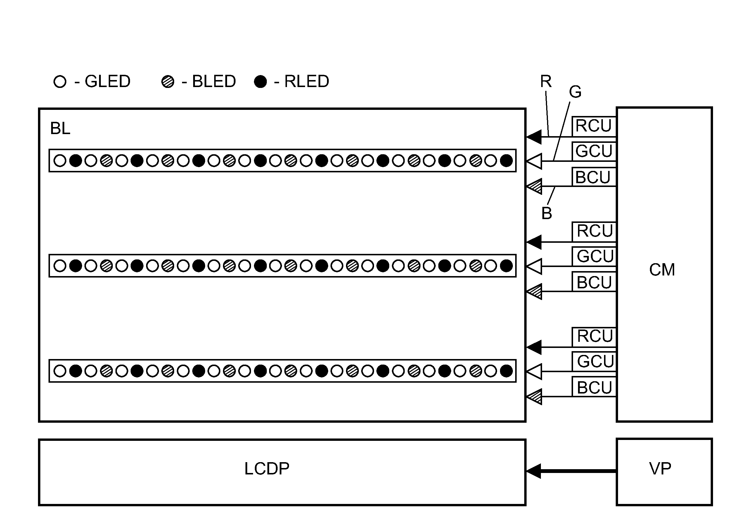
[0027]FIG. 1 shows a basic representation of a liquid crystal display device according to the invention. The liquid crystal display device comprises a LCD display panel LCDP, optionally a video processing unit VP, a backlight means BL and a control means CM for controlling the backlight means BL. The backlight means BL comprises a plurality of colored light-emitting device LED, i.e. green LEDs GLED, red LEDs RLED and blue LEDs BLED. The LEDs are arranged in rows or horizontal stripes. Although in FIG. 1 only three rows of LEDs are depicted, the backlight means BL may comprise more than merely three rows LEDs. Each row of LEDs or each horizontal stripe of LEDs are driven by a control unit for red RCU, a control unit for green GCU and control unit for blue BCU. In other words, the control units RCU, GCU and BCU are associated to each of the rows of LEDs for controlling the colored LEDs in that row. The LCD panel LCDP is used to display the images and video signals from the internal or...

second embodiment

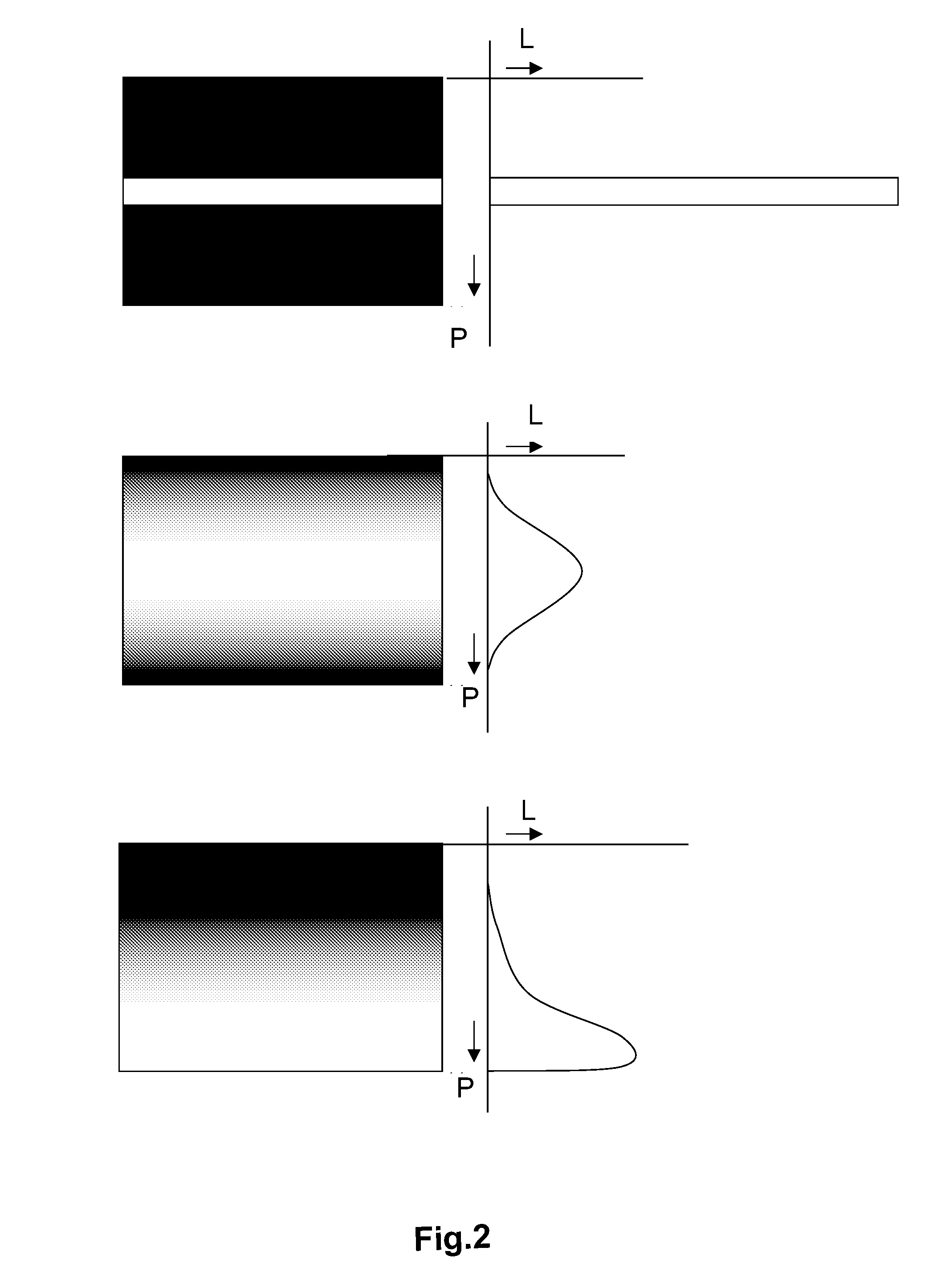
[0032]FIG. 4 shows a diagram of the light output L of red R, green G and blue B sub-pixels for double-pulse scanning backlight according to a Instead of merely one scanning pulse as described according to FIG. 3, the double-pulse scanning backlight according to FIG. 4 has a primary and a secondary pulse P, S at t1 and t3 within one time period T, respectively. Accordingly, the primary pulse P will comprise a primary green pulse PG, a primary red pulse PR and a primary blue pulse PB while the secondary pulse S will comprise a secondary green pulse SG, a secondary red pulse SR and a secondary blue pulse SB. Preferably, the primary pulses PG, PR and PB are aligned at t1, i.e. immediately before the liquid crystal cells of the LCD panel are addressed by the next frame of the video data corresponding to that moment when the liquid crystal cells are optimally settled. On the other hand, the secondary pulse SG, SR, SB are aligned in the middle of two subsequent primary pulses P, i.e. at t...

third embodiment

[0034]FIG. 5 shows a diagram of a double-pulse scanning backlight according to a Here, the red R, green G and blue B pulses of the primary and secondary pulse P, S of the double-pulse scanning are aligned at the centers of the respective pulses, i.e. at t4, t5, respectively. Hence, by such an alignment, the blurring on various edges of objects is now symmetrical.

[0035]FIG. 6 shows a diagram to illustrate the primary and secondary pulses of a double-pulse scanning backlight according to a fourth embodiment. Here, the duty cycles of the red R, blue B and green G sub-pixels correspond to each other to enable a bright and sharp exposure of the primary pulse wherein the centers of the duty cycles are aligned at t4. The duty cycles of the red R, green G and blue B sub-pixels are different for the secondary pulse and the centers of the red R, green G and blue B pulses are aligned at t5 as described according to the third embodiment. By providing different duty cycles for the secondary sub...


PUM


Abstract

A liquid crystal display device is provided, comprising a liquid crystal display panel (LCDP) for displaying an image or a video signal. The display device furthermore comprises a double-pulse scanning backlight means (BL) having a plurality of red, green and blue colored light emitting diodes (RLED, GLED, BLED) arranged in rows for backlighting the liquid crystal display panel (LCDP) on a double-pulse scanning basis. Furthermore, a double-pulse scanning control means (CM) is provided for controlling the time sequential double-pulse scanning of the plurality of colored light emitting diodes (RLED, GLED, BLED) of the backlight means (BL) and for driving the time sequential double-pulse scanning of the plurality of colored light emitting diodes (RLED, GLED, BLED).

Description

FIELD OF THE INVENTION[0001]The present invention relates to a liquid crystal display device and a method for driving a liquid crystal display device.BACKGROUND OF THE INVENTION[0002]In order to improve the performance of a liquid crystal display (LCD) device, LCD backlights are used in particular to enhance the brightness of the displayed images or video signals. Previously, side-lit backlights have been used but have been recently replaced by direct-lit backlights as direct-lit backlights improve the brightness of larger size LCD and TV devices.[0003]The continuous lit backlights can be replaced by scanning backlights to further improve the picture quality of a LCD device. By means of scanning backlights motion artifacts which result from sample and hold effects of the LCD panel can be reduced. Back-lit LCD backlights may comprise fluorescence lamps like cold cathode fluorescence lamps CCFL or hot cathode fluorescence lamps HCFL. Typically, a number of fluorescence lamps are arran...

Claims


Application Information

Patent Timeline
IPC IPC(8): G09G3/36G02F1/13357
CPCG09G3/3413G09G3/342G09G3/3611G09G2320/064G09G2320/0242G09G2320/0247G09G2320/0261G09G2310/024G02F1/133G09G3/20G09G3/32G09G3/36
Inventor DE GREEF, PETRUS M.
Owner NXP BV
Why Eureka
Try Eureka