[0007]However, in the case where the
light emission quantity of the LED is controlled by the feedback
system using a photoreception device, there is a
disadvantage as follows. That is, in the backlight device that performs lighting operation by using the plurality of partial lighting sections, a signal value varies according to timing of sampling a photoreception signal obtained by the photoreception device, and thus detection precision of the illuminated light is lowered.
[0010]In view of the foregoing
disadvantage, it is an object of the present invention to provide a light source device capable of improving detection precision of illuminated light in the light source device performing partial lighting operation and a
liquid crystal display unit including such a light source device.
[0013]In the light source device and the
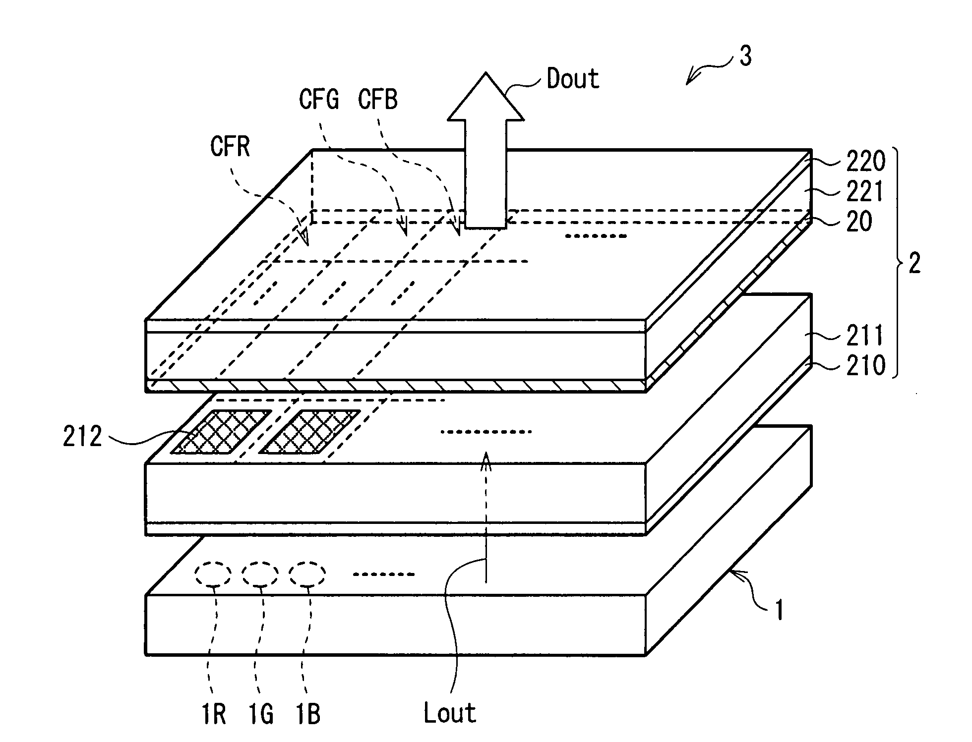
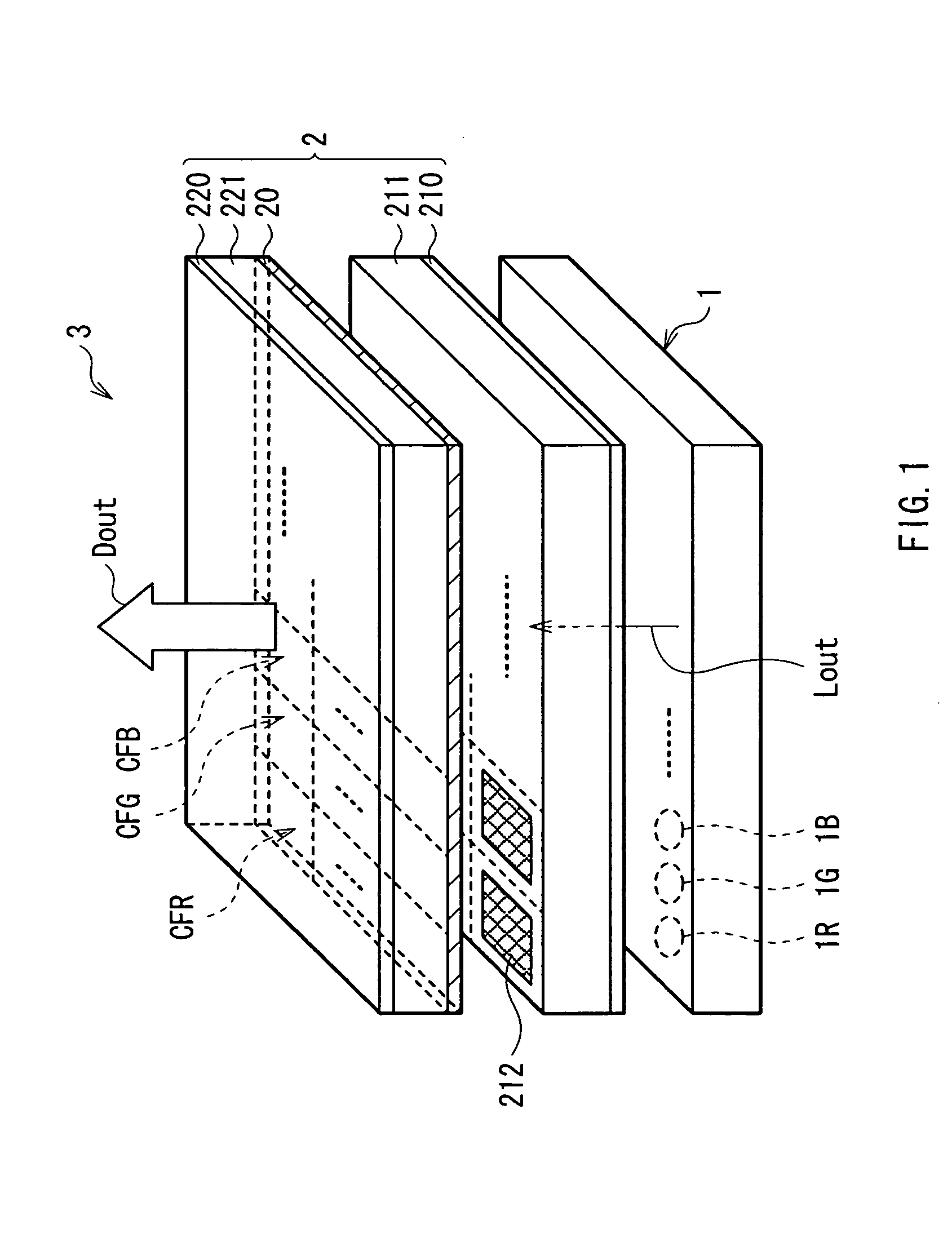
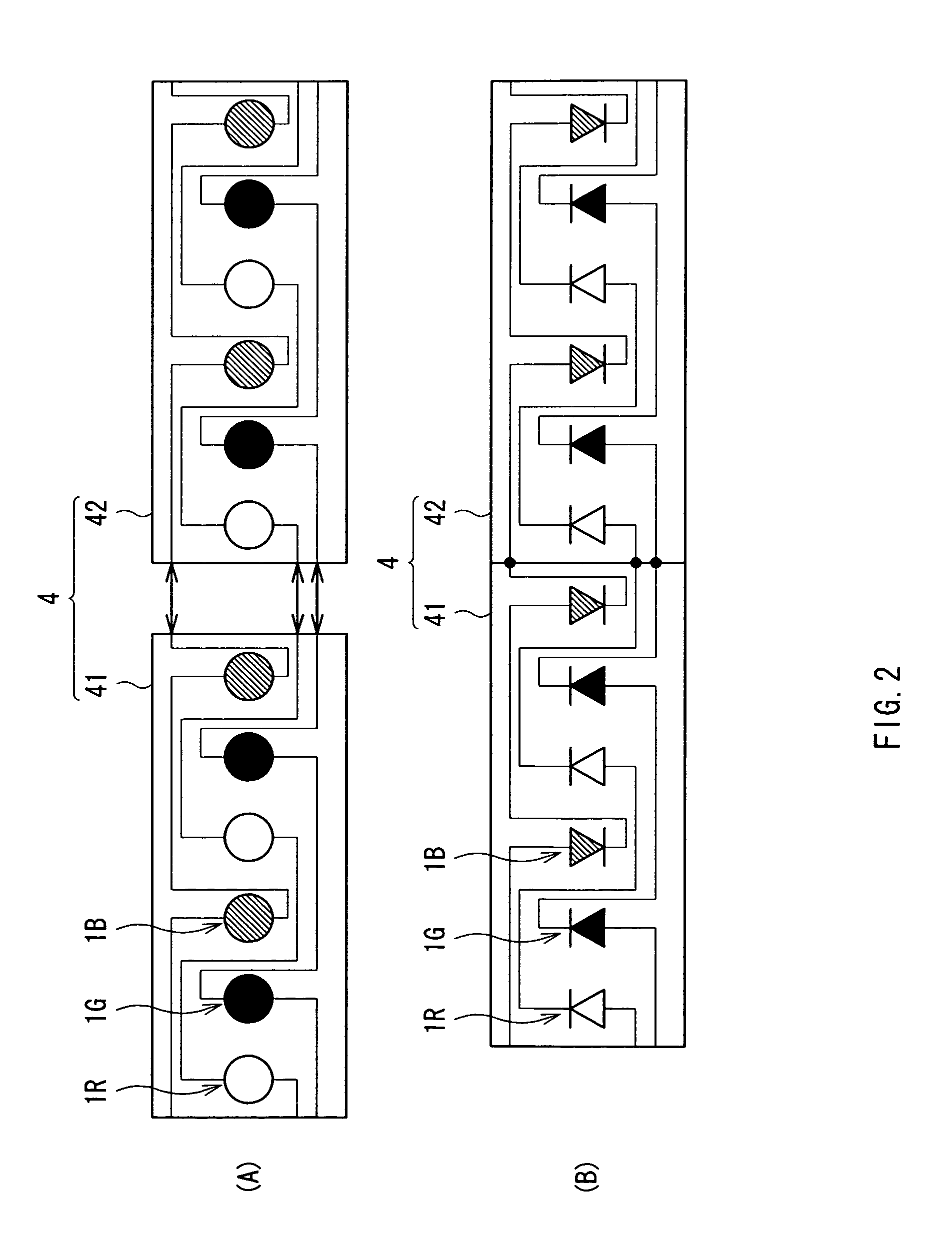
liquid crystal display unit of the present invention, the light source section is time-divisionally driven by a pulse signal so that the whole lighting time period and the partial lighting time period are mixed along time base, and light from the light source section is received by the photoreception device. The width of the pulse signal (last pulse signal) generated immediately before a transition from the whole lighting time period to the partial lighting time period are equal to or less than a given threshold value, and the photoreception signal obtained by the photoreception device is sampled at a timing in the partial lighting time period. Thus, even if the light emission luminance of the partial lighting section is set high (even if the width of the foregoing last pulse signal is set to be wider than the threshold value), the width of the last pulse signal is forcefully the threshold value or less. Therefore, interference between the photoreception signal obtained in the whole lighting time period and the photoreception signal obtained in the last partial lighting time period is able to be avoided. Accordingly, a signal value of the photoreception signal in the partial lighting time period is able to be almost constant not depending on sampling timing in the partial lighting time period.
[0014]In the light source device of the present invention, the foregoing drive means may perform control so that the light emission quantity of each of the partial lighting sections is respectively kept constant based on the photoreception signal sampled by the sampling means in the partial lighting time period. In this case, the light emission quantity of each of the partial lighting sections is respectively controlled based on the photoreception signal in the partial lighting time period whose value is kept almost constant not depending on sampling timing, and thus precision to keep the light emission quantity constant is improved. Further, the foregoing drive means may perform control so that the light emission quantity of the one part of the partial lighting sections is respectively kept constant based on the photoreception signal sampled by the sampling means in the partial lighting time period, and the foregoing drive means may drive the light source section so that the one part of the partial lighting sections circularly travels in the plurality of partial lighting sections. In this case, again, the light emission quantity of the foregoing one part of the partial lighting sections is respectively controlled based on the photoreception signal in the partial lighting time period whose value is kept almost constant not depending on sampling timing, and thus precision to keep the light emission quantity constant is improved. Further, since the one part of the partial lighting sections whose light emission quantity is the control target circularly travels in the plurality of partial lighting sections, light emission quantities of the all partial lighting sections are controlled based on their own illuminated light. Accordingly, fine light emission quantity control for the respective partial lighting sections is enabled, and precision to keep the light emission quantity constant as the whose light source section is more improved.
[0015]In the light source device of the present invention, the foregoing drive means preferably performs configuration so that the threshold value decreases as a frequency of the pulse signal increases. In this case, it is possible to address a case that the frequency of the pulse signal is changed. Thus, even if the frequency is high, interference between the photoreception signal in the whole lighting time period and the photoreception signal in the partial lighting time period is able to be avoided.
[0016]According to the light source device or the
liquid crystal display unit of the present invention, the light source section is time-divisionally driven by the pulse signal so that the whole lighting time period and the partial lighting time period are mixed along time base, and light from the light source section is received by the photoreception device. The width of the pulse signal (last pulse signal) generated immediately before the transition from the whole lighting time period to the partial lighting time period are equal to or less than the given threshold value, and the photoreception signal obtained by the photoreception device is sampled at the timing in the partial lighting time period. Thus, even if the light emission luminance of the partial lighting section is set high (even if the width of the foregoing last pulse signal is set to be wider than the threshold value), interference between the photoreception signal obtained in the whole lighting time period and the photoreception signal obtained in the last partial lighting time period is able to be avoided. Accordingly, a signal value of the photoreception signal in the partial lighting time period is able to be almost constant not depending on sampling timing in the partial lighting time period, and detection precision of illuminated light is able to be improved in the light source device performing partial lighting operation.


