Optical unit with shake correcting function and shake correction control method therefor

a technology of shake correction and optical units, applied in the direction of instruments, television systems, camera body details, etc., can solve the problems of increasing the number of components including the sensor, the response of correction is not rapid, and the control system becomes complicated, so as to achieve the effect of simple control system and rapid correction

Inactive Publication Date: 2010-04-22
SANKYO SEIKI MFG CO LTD
View PDF1 Cites 101 Cited by
  • Summary
  • Abstract
  • Description
  • Claims
  • Application Information

AI Technical Summary

Benefits of technology

[0006]In view of the problems described above, at least an embodiment of the present invention may advantageously provide an optical unit with shake correcting function in which a shake can be rapidly corrected with a simple control system and provide a shake correction control method for the optical unit with shake correcting function.

Problems solved by technology

However, in a conventional optical unit, an angular velocity signal corresponding to a shake is integrated to obtain an angular displacement by a gyroscope which is used as a shake detection sensor and a movable module is displaced so as to correspond to the angular displacement and thus response of correction is not rapid.
Therefore, the control system becomes complicated and the number of components including the sensor is increased.

Method used


Image

  • Optical unit with shake correcting function and shake correction control method therefor
  • Optical unit with shake correcting function and shake correction control method therefor
  • Optical unit with shake correcting function and shake correction control method therefor

Examples


Embodiment Construction

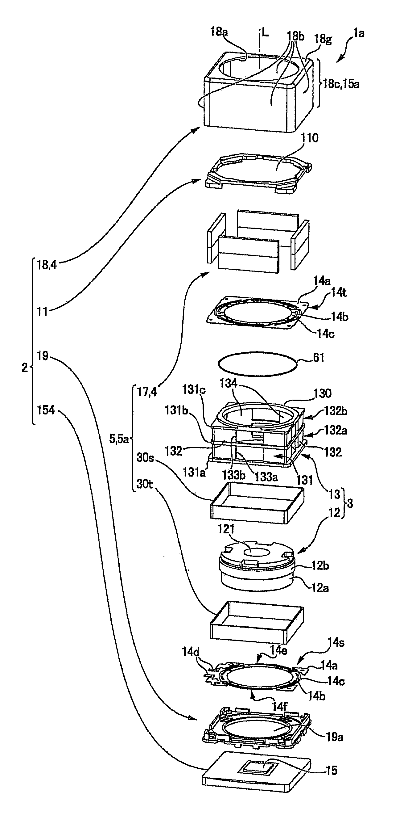
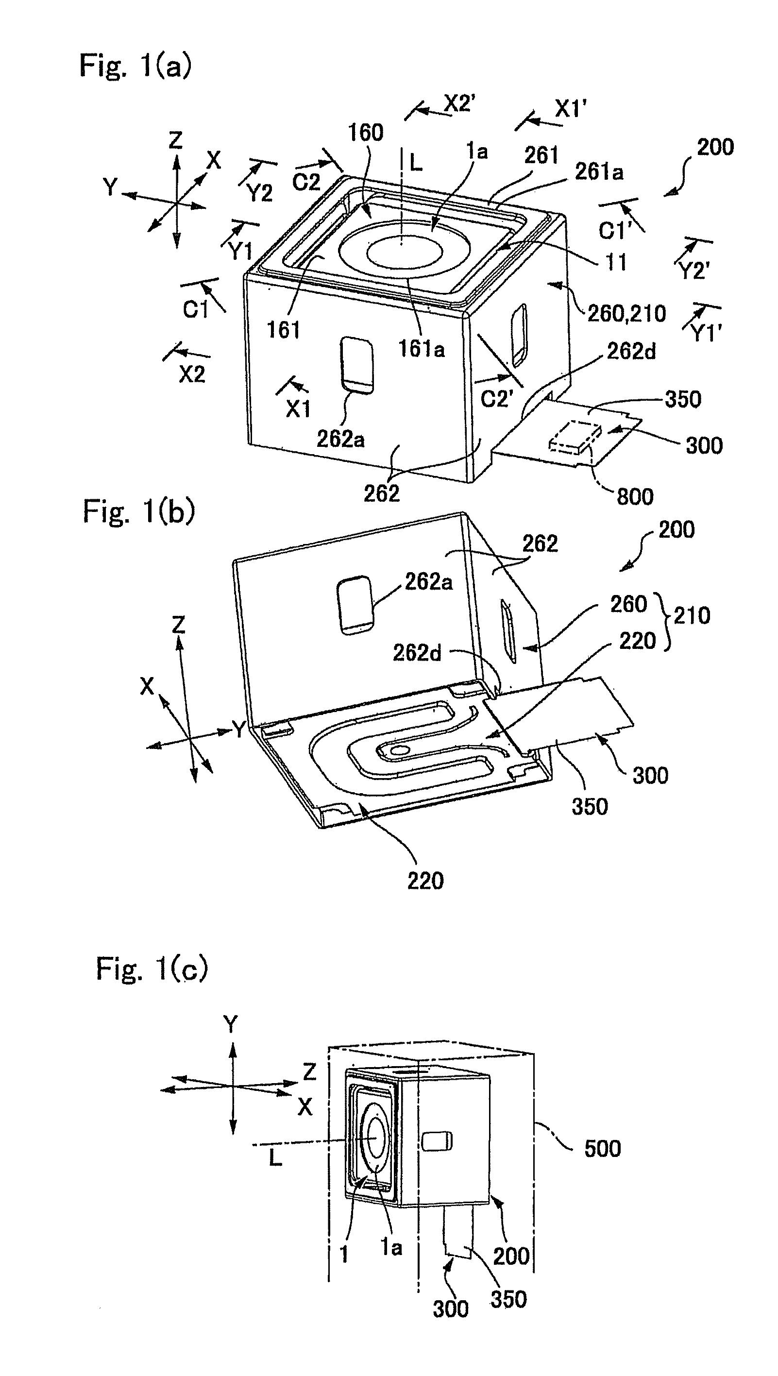
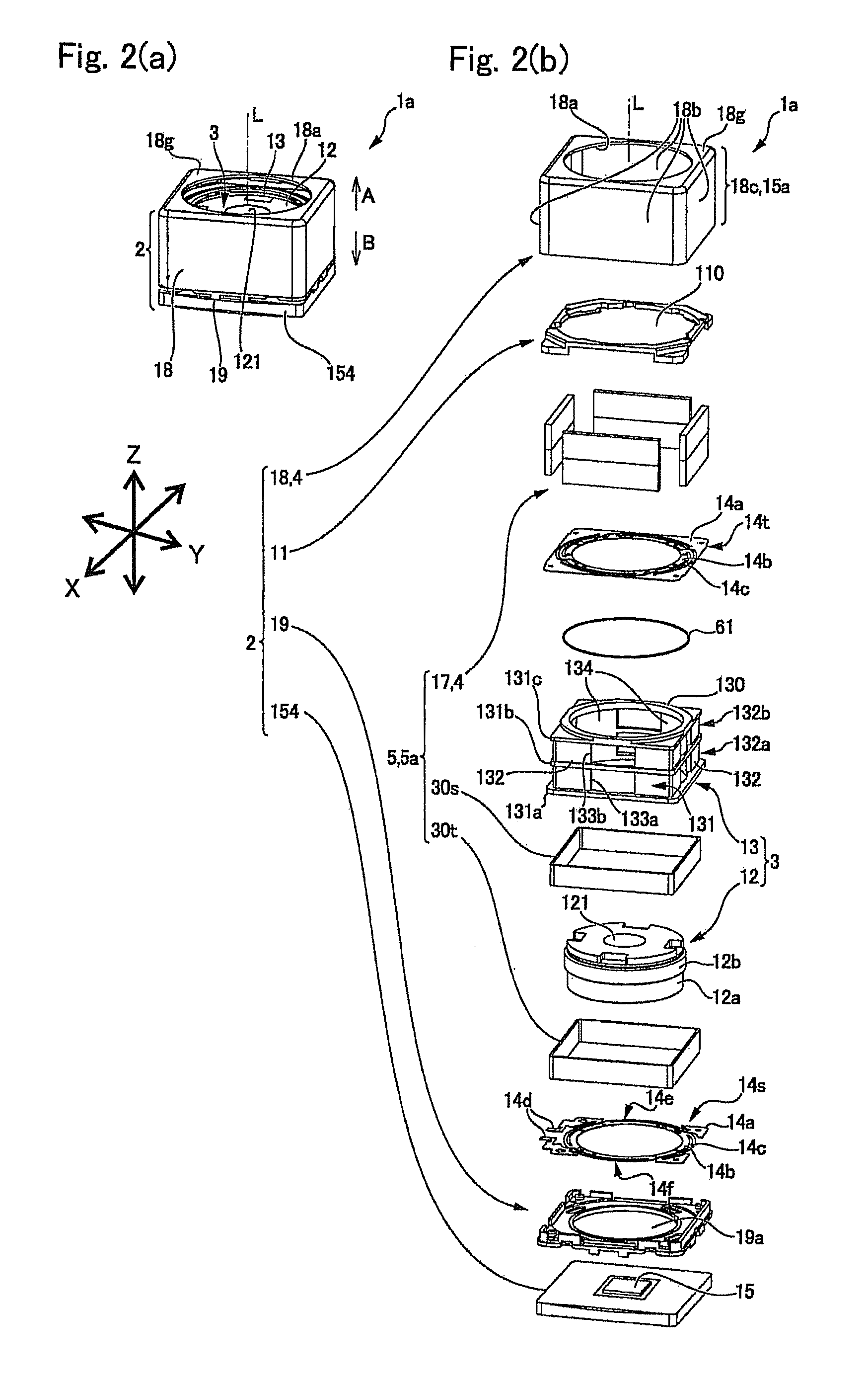
[0042]An embodiment of the present invention will be described below with reference to the accompanying drawings. In the following description, three directions perpendicular to each other, i.e., an X-axis, a Y-axis and a Z-axis are set in a fixed body, and the direction along an optical axis “L” (lens optical axis) is set to be the Z-axis. Therefore, in the following description, swing around the X-axis corresponds to a so-called pitching (vertical swing), swing around the Y-axis corresponds to a so-called yawing (lateral swing) and swing around the Z-axis corresponds to a so-called rolling. Further, in the following description, “object to be photographed side” is described as “front side” or “upper side”, and “opposite side to the object to be photographed side” is described as “rear side” or “lower side”.

[0043]FIGS. 1(a), 1(b) and 1(c) are explanatory views showing an entire optical unit with shake correcting function in accordance with an embodiment of the present invention. FI...


PUM


Abstract

An optical unit with shake correcting function may include a movable module on which at least an optical element is mounted, a fixed body which supports the movable module, a shake detection sensor which detects a shake of the movable module, a drive mechanism for shake correction for swinging the movable module on the fixed body on the basis of a detection result of the shake detection sensor to correct the shake of the movable module, and a control section which controls the drive mechanism for shake correction on the basis of the detection result of the shake detection sensor. The shake detection sensor is a gyroscope mounted on the movable module and the control section controls the drive mechanism for shake correction so as to cancel the shake detected by the gyroscope.

Description

CROSS REFERENCE TO RELATED APPLICATION[0001]The present invention claims priority under 35 U.S.C. §119 to Japanese Application No. 2008-270142 filed Oct. 20, 2008, and Japanese Application No. 2009-218197 filed Sep. 19, 2009, the entire contents of which are incorporated herein by reference.FIELD OF THE INVENTION[0002]An embodiment of the present invention may relate to an optical unit with shake correcting function in which a movable module having a lens is swung to correct a shake such as a hand shake and may relate to a shake correction control method for the optical unit with shake correcting function.BACKGROUND OF THE INVENTION[0003]In a photographic optical device, which is mounted on a cell phone or a digital camera, a laser beam pointer, or an optical instrument such as a portable projection display device or a projection display device for a car, a shake is easily occurred in its optical axis when a shake or external vibration is transmitted.[0004]In order to prevent this p...

Claims


Application Information

Patent Timeline
Patent Type & Authority Applications(United States)
IPC IPC(8): G03B17/00G02B27/64
CPCG02B27/646H04N5/23287H04N5/2257G03B17/00H04N23/57H04N23/687
Inventor ISHIHARA, HISAHIROKARASAWA, TOSHIYUKIMINAMISAWA, SHINJITAKEI, YUICHITAKEDA, TADASHIYANAGISAWA, KATSUSHIGENAGATA, AKIHIROMIYAZAKI, KIYOSHI
Owner SANKYO SEIKI MFG CO LTD
Why Eureka
Try Eureka