

Honeycomb Structure
a honeycomb and structure technology, applied in the direction of machines/engines, metal/metal-oxide/metal-hydroxide catalysts, chemical/physical processes, etc., can solve the problems of increased load on the engine, large pressure loss, etc., and achieve low initial pressure loss, high filtration efficiency of pms in the exhaust gas, and increase in pressure loss
Active Publication Date: 2010-04-22
TYK CORP
View PDF1 Cites 9 Cited by
- Summary
- Abstract
- Description
- Claims
- Application Information
AI Technical Summary
Benefits of technology
The present invention aims to provide a honeycomb structure that has high filtration efficiency of particulate matters (PMs) in the exhaust gas, low initial pressure loss, and suppressed increase in pressure loss in accompanied with the trapping of PMs.
Problems solved by technology
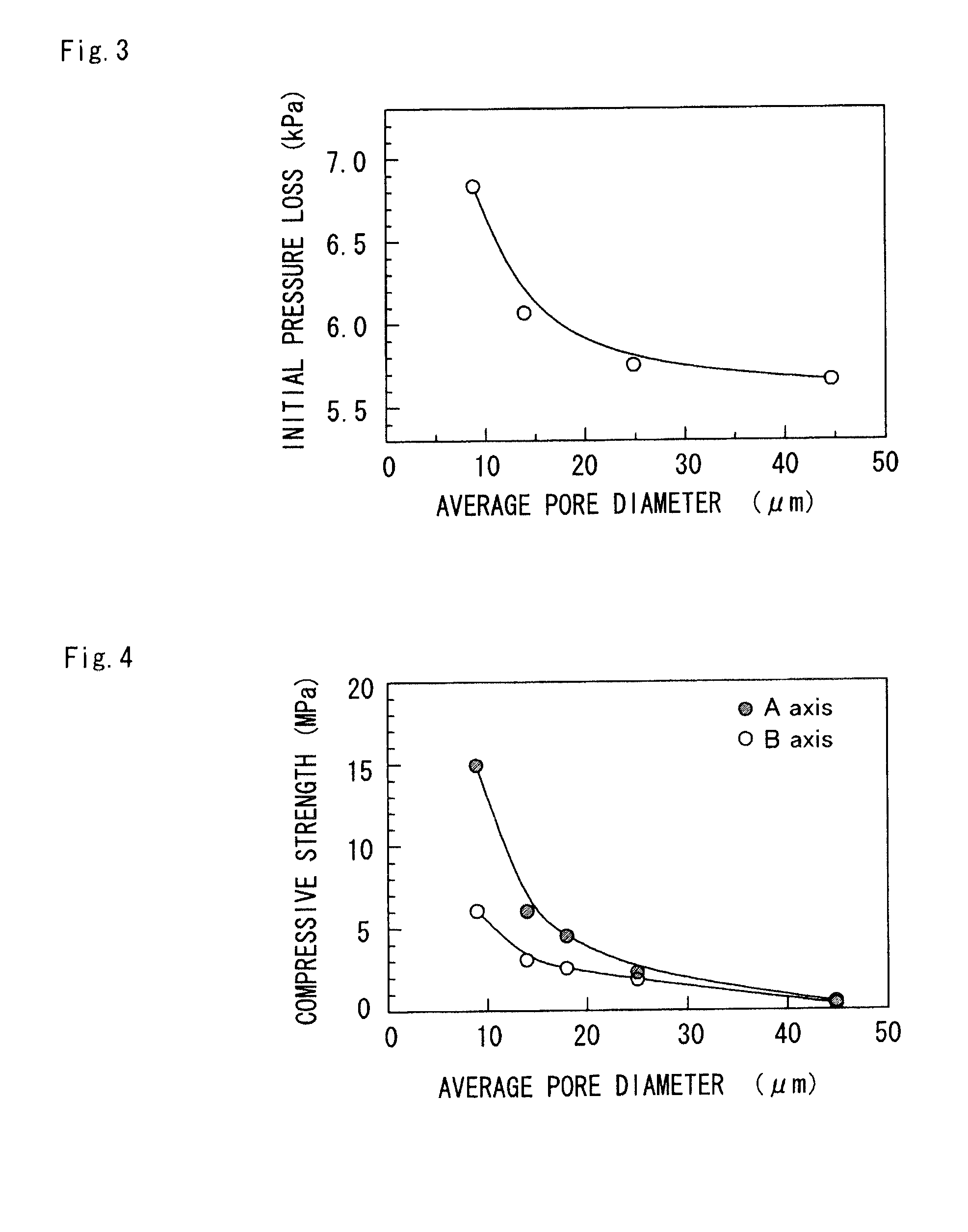
On the other hand, when pore diameters are too small, pressure loss becomes large due to resistance to passage of the gas so that the load on the engine is increased.
Method used
View moreImage
Smart ImageViewing Examples

Examples
example
COMPARATIVE EXAMPLE 1
COMPARATIVE EXAMPLE 2
COMPARATIVE EXAMPLE 3
[0053]LOGARITHMIC DIFFERENTIATION PORE VOLUME dv / d(logD) [10−3 m3 / kg]
PORE DIAMETER (μm)
FIG. 7
example
COMPARATIVE EXAMPLE 1
COMPARATIVE EXAMPLE 2
COMPARATIVE EXAMPLE 3
[0054]CUMULATIVE PORE VOLUME [10−3 m3 / kg]
PORE DIAMETER D (μm)
FIG. 8
example
COMPARATIVE EXAMPLE 1
COMPARATIVE EXAMPLE 2
COMPARATIVE EXAMPLE 3
[0055]PRESSURE LOSS (kPa)
DEPOSITION AMOUNT OF PARTICULATE MATTER (kg / m3)
FIG. 9
FILTRATION EFFICIENCY (%)
Login to View More PUM
| Property | Measurement | Unit |
|---|---|---|
| pore diameter | aaaaa | aaaaa |
| pore diameter | aaaaa | aaaaa |
| pore diameter | aaaaa | aaaaa |
Abstract
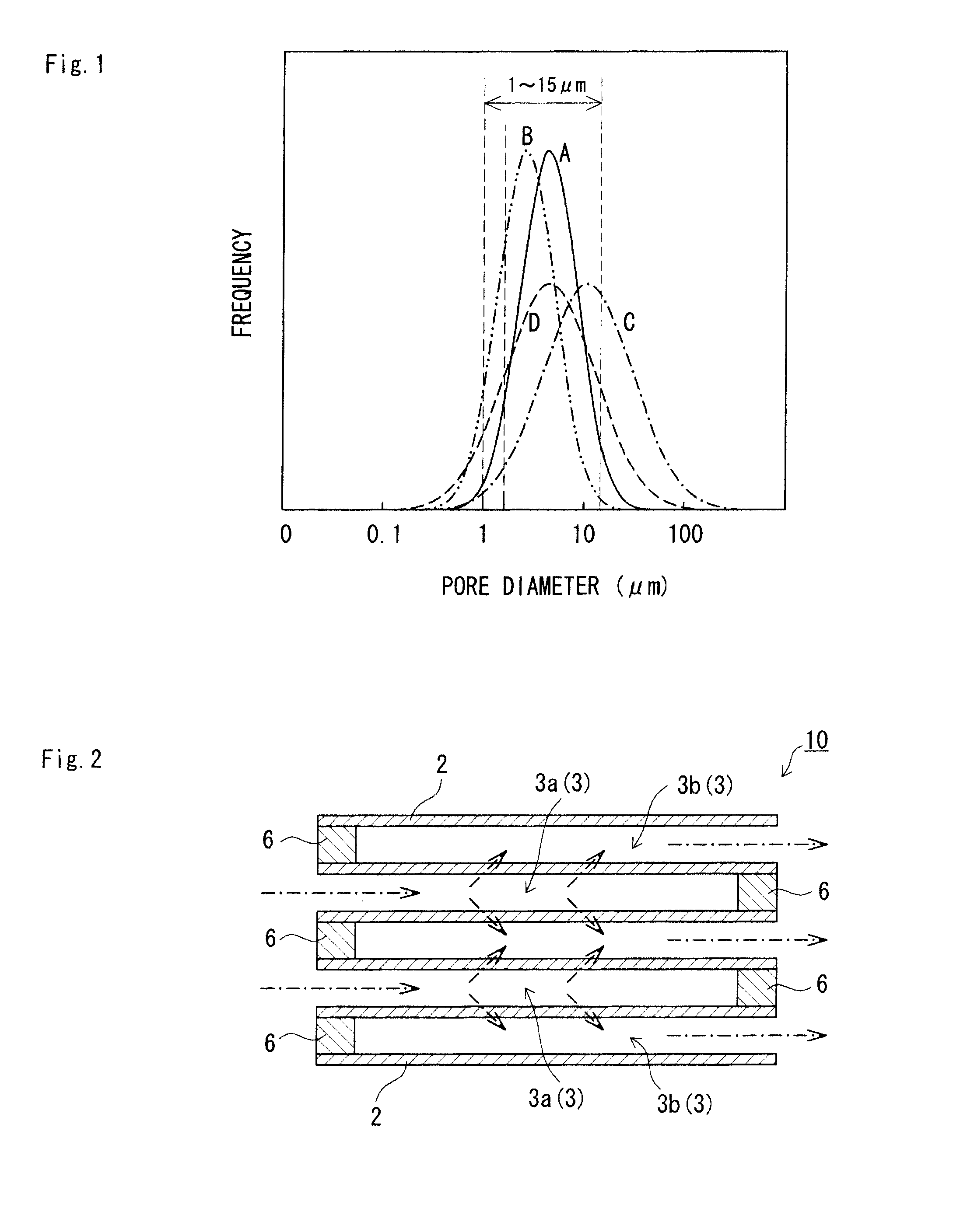
There is provided a honeycomb structure in which filtration efficiency of particulate matters (PM) in the exhaust gas is high, initial pressure loss is low and increase in pressure loss in accompanied with the trapping of PMs is suppressed.The honeycomb structure includes a plurality of cells partitioned by a plurality of partition walls which are made of silicon carbide porous ceramics and are lined up in a single direction, an average pore diameter of the partition walls measured by mercury porosimetry is 1 μm to 15 μm, a standard deviation in a pore diameter distribution is 0.20 or less when the pore diameter is represented by common logarithm, and percentage of the pores having the pore diameter of less than 2 μm relative to the entire pores is 5 vol % or less.
Description
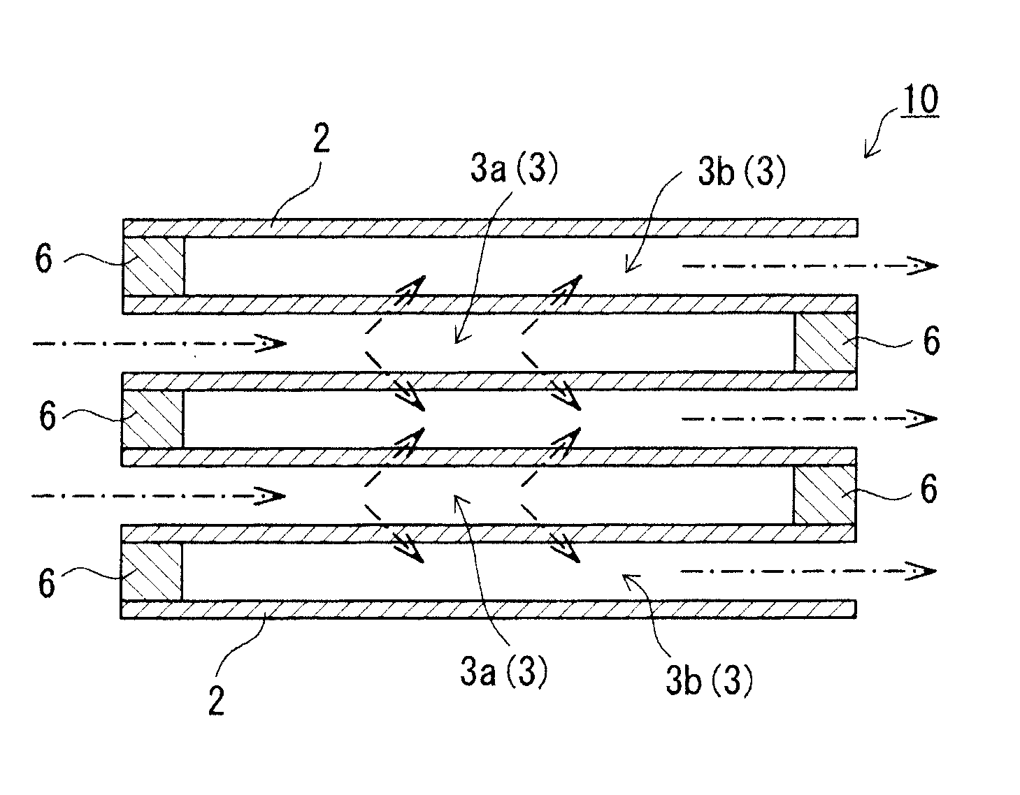
TECHNICAL FIELD[0001]The present invention relates to a honeycomb structure, in particular, to a honeycomb structure suitable for removing particulate matters from the exhaust gas of a diesel engine.BACKGROUND ART[0002]A honeycomb structure including a plurality of cells partitioned by a plurality of partition walls which are made of porous ceramics and are lined up in a single direction is conventionally used as a filter which traps and removes particulate matters (hereinafter, referred to as “PM”) such as soot contained in the gas exhausted from a diesel engine. In such a honeycomb structure, generally, cells one ends of which are sealed and cells the other ends of which are sealed are alternatively arranged. The gas flows in from the cells opened in one direction, passes through the porous partition walls, and flows out from the cells opened in the other direction. Then, when the gas passes through the partition walls, PMs in the gas are trapped and removed through surfaces and p...
Claims
Login to View More Application Information
Patent Timeline
 Patent Type & AuthorityApplications(United States)
IPC IPC(8): B32B3/12
CPCB01D46/2429Y10T428/24149B01D2046/2496B01D2255/1021B01D2255/1023B01D2255/1025B01D2255/202B01D2255/204B01D2258/012B01D2275/30B01J23/58C04B35/185C04B35/195C04B35/478C04B35/565C04B35/584C04B38/0009C04B2111/00793C04B2111/0081F01N3/0222B01D2046/2437C04B38/0054B01D46/24492B01D46/2498
InventorTSUNEYOSHI, KOJITAKAGI, OSAMU
OwnerTYK CORP