Gel cushion

a gel cushion and gel technology, applied in the field of gel cushion, can solve the problems of affecting the comfort of users, pads suffer from a number of disadvantageous performance characteristics, and the cushioning provided is either too large, so as to avoid the discomfort of heat and/or swea

Inactive Publication Date: 2010-04-22
POOLE HLDG
View PDF8 Cites 10 Cited by
  • Summary
  • Abstract
  • Description
  • Claims
  • Application Information

AI Technical Summary

Benefits of technology

[0008]The resilient material is preferably formed of a polymer gel, or other suitable material, whereby the mounds may preferably deform, at least partially, in a compression direction, i.e. in a direction perpendicular to the generally planar surface, in response to a force applied thereto while resisting such a force, such as a force imparted to the mounds when a user rests thereon. Thus, the resilient mounds preferably cushion a portion of a user's body disposed thereagainst, especially when bearing the user's weight. The resilient material and / or the substantially hemispherical or ellipsoidal shape of the mounds preferably provide(s) an increasing resistance force and preferably deform to a greater extent in response to an increasing load applied thereto. Accordingly, the mounds preferably accommodate users of different weight, and provide sufficient cushioning to comfort a user resting thereon.
[0009]Additionally, the selective arrangement of the rows of mounds preferably provides stability to a user resting thereon. For example, two rows may be arranged generally proximate and on opposite sides of a longitudinal axis of the cushion. Thus, when a user places a portion of their body generally centrally on the cushion, the rows preferably straddle the portion of the user's body and resist lateral movement of the user's body relative to the cushion. Such resistance of lateral movement is preferably provided by mounds of each row generally retaining the user's body, or at least the portion thereof, partially between adjacent mounds of each row. Furthermore, the resilient material and / or the substantially hemispherical or ellipsoidal shape of the mounds preferably provide(s) a resistance force to oppose lateral or shear forces. Such lateral or shear resistance force may preferably result in less lateral deformation than a compression deformation exhibited in response to an equal force in the compression direction.
[0011]Accordingly, one feature and advantage of the cushion of the present disclosure is its ability to provide cushioning substantially proportionate to a force applied thereto, whereby relatively smaller forces are cushioned by partial deformation of a resilient material, and whereby incremental increases in a force applied to the resilient material result in sequentially smaller amounts of additional deformation.
[0012]Another feature and advantage of the cushion of the present disclosure is its ability to securely cushion a portion of a user's body by resistance of lateral forces and / or via at least partially cupping the portion of the user's body.
[0013]Yet another feature and advantage of the cushion of the present disclosure is its ability to resist or prevent accumulation of excess thermal energy, whereby discomfort associated with heat and / or sweating may be avoided.

Problems solved by technology

As is well known, prolonged periods of exposure to such forces and / or exposure to repetitive forces can cause or contribute to the development or onset of tissue and / or bone damage or injury.
Unfortunately, however, such pads suffer from a number of disadvantageous performance characteristics.
Since the pads are all made with substantially the same amount of padding material, most users find that the cushioning provided is either too great, wherein the pad is not stable, or wherein the cushioning provided is too little, wherein the user experiences discomfort due to complete compression or deformation of the padding material.
Additionally, and especially where a conforming cup is provided, the padding functions as a thermal insulator, whereby the user's skin may become hot, sweaty, and uncomfortable, and whereby the pad may experience premature wear and / or may become excessively soiled.
Furthermore, conventional cushion materials are directionally unbiased, whereby in addition to compressing in a desired direction, the cushion may also shear or deform in directions other than the desired direction.
Such off-axis compression or deformation causes unsteadiness, which can sap a wearer's energy due to the constant need to shift position or weight to maintain or regain balance.

Method used


Image

  • Gel cushion
  • Gel cushion

Examples


Embodiment Construction

[0018]In describing the cushion of the present disclosure illustrated in the drawing, specific terminology is employed for the sake of clarity. The claimed invention, however, is not intended to be limited to the specific terminology so selected, and it is to be understood that each specific element includes all technical equivalents that operate in a similar manner to accomplish a similar purpose.

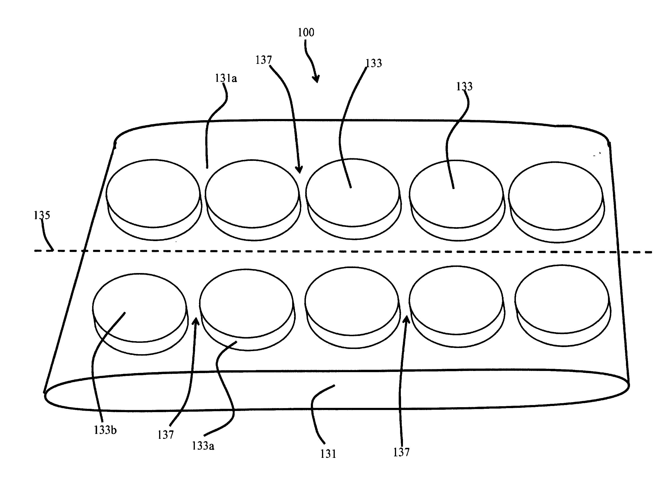
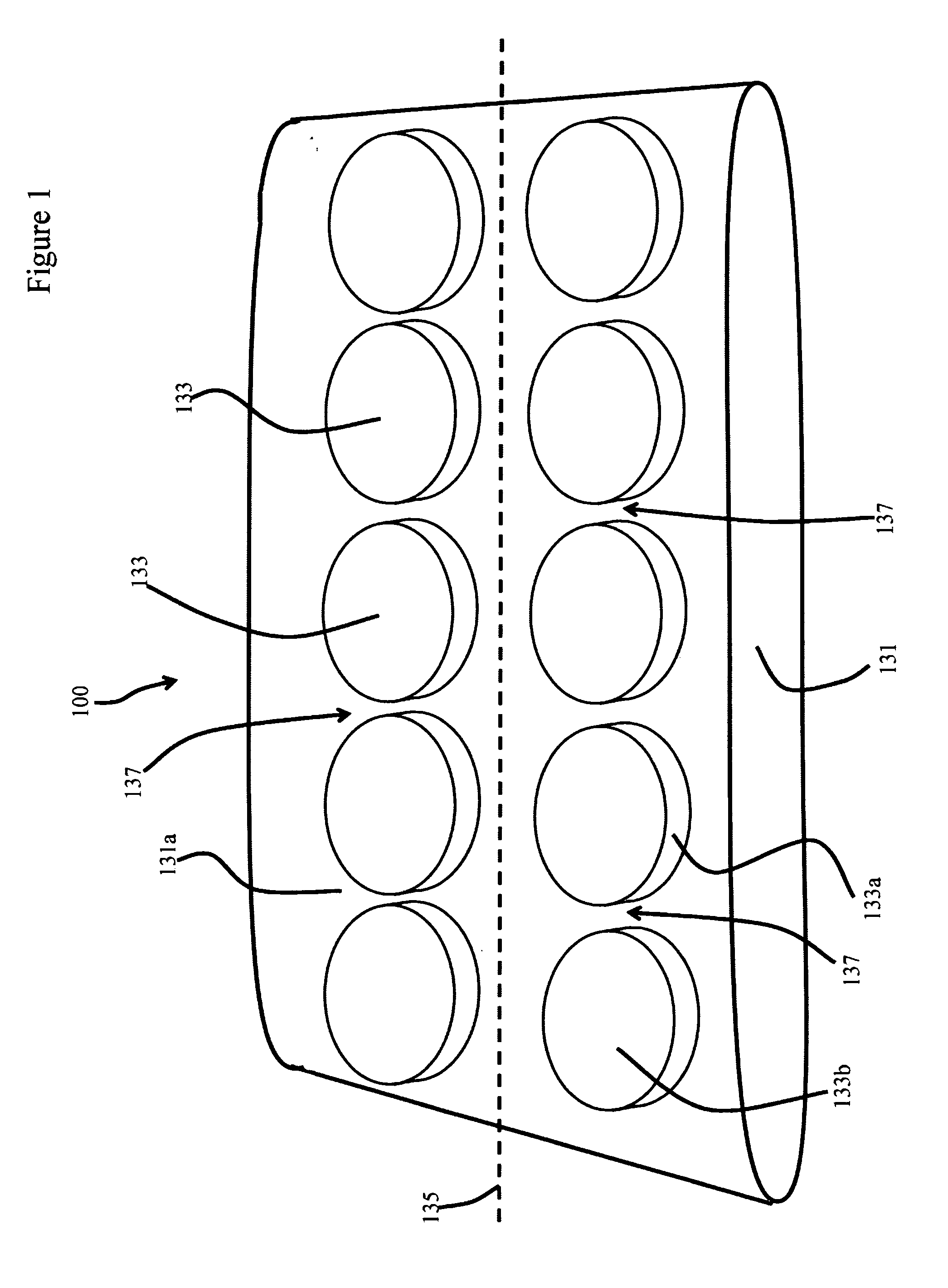
[0019]In that form of the cushion of the present disclosure chosen for purposes of illustration, FIG. 1 shows cushion 100 including two or more mounds 133 formed over face 131a of generally thin planar member 131. Mounds 133 disposed over face 131a of planar member 131 are preferably arranged in an array, including two rows of two or more mounds 133. As illustrated, resilient member 130 includes 10 mounds 133 arranged in two parallel rows disposed on opposite sides of central longitudinal axis 135. As will be understood by those ordinarily skilled in the art, other numbers of mounds 133 an...


PUM

PropertyMeasurementUnit
forceaaaaaaaaaa
compression forceaaaaaaaaaa
resilientaaaaaaaaaa

Abstract

A gel cushion, such as may be incorporated in a knee pad or other body-worn pad, that avoids undue accumulation of heat within the cushion, and that provides a stable and comfortable resting surface for at least a portion of a user's body. The cushion may further provide decreasing incremental compression in response to incrementally increasing loads, whereby users of different weights may be comfortably supported thereon.

Description

CROSS REFERENCE TO RELATED APPLICATIONS[0001]This application claims the benefit of U.S. Utility application Ser. No. 12 / 387,763 filed on May 6, 2009 currently pending the contents of which is hereby incorporated by reference, which in turn claimed priority to U.S. Provisional Application Ser. No. 61 / 050,975 filed on May 6, 2008, presently abandoned, the contents of which is hereby incorporated by reference.TECHNICAL FIELD[0002]The present disclosure relates generally to force absorbing devices, and, more particularly, to a gel cushion having a plurality of convex projections.BACKGROUND OF THE INVENTION[0003]Various activities, such as many occupational activities, recreational activities, or the like, involve repetitive forces. For example, activities that require kneeling for some duration of time impart forces to an individual's knees. As is well known, prolonged periods of exposure to such forces and / or exposure to repetitive forces can cause or contribute to the development or ...

Claims


Application Information

Patent Timeline
Patent Type & Authority Applications(United States)
IPC IPC(8): B32B3/30
CPCA41D13/065A41D31/0044Y10T428/24612Y10T428/24661A41D13/015A41D31/28
Inventor HANLON, JARED
Owner POOLE HLDG
Why Eureka
Try Eureka