
Waste Heat Utilization Device for Internal Combustion Engine

a technology for internal combustion engines and waste heat, which is applied in the direction of machines/engines, mechanical equipment, transportation and packaging, etc., can solve the problems of insufficient cooling of the engine, high gwp (global warming potential), and possible ignition or worst, explosion of alternative cfcs, etc., and achieve the effect of more safe and proper operation

Active Publication Date: 2010-04-29
SANDEN CORP
View PDF9 Cites 30 Cited by
  • Summary
  • Abstract
  • Description
  • Claims
  • Application Information

AI Technical Summary

Benefits of technology

[0006]The present invention has been made in view of problems as mentioned above. The primary object of the present invention is to provide a waste heat utilization device for an internal combustion engine which allows a Rankine cycle circuit using a combustible refrigerant to function safely and properly.
[0007]In order to achieve the above object, a waste heat utilization device for an internal combustion engine according to the present invention is designed to recover waste heat produced by the internal combustion engine from a heat medium, and comprises a Rankine cycle circuit including an evaporator, an expander, a condenser and a pump serially arranged in a circulation line along which a combustible working fluid circulates, where the evaporator transfers heat from the heat medium to the working fluid, the expander expands the working fluid that has passed through the evaporator, thereby producing drive power, the condenser condenses the working fluid that has passed through the expander, and the pump forces the working fluid that has passed through the condenser toward the evaporator, a casing air-tightly enclosing the Rankine cycle circuit, and an inactivation means for creating a chemically-inactive condition inside the casing.
[0008]The above-described waste heat utilization device for the internal combustion engine can prevent the combustible working fluid that has leaked from the Rankine cycle circuit from undergoing oxidation reaction and igniting, etc., resulting in an improved safety of the Rankine cycle circuit and therefore of the waste heat utilization device.

Problems solved by technology

Such alternatives for CFC have, however, a very high GWP (Global Warming Potential), so that there still exists a concern about their environmental impact.
If this refrigerant leaks from the circulation line, the evaporator, the expander or the like, it may possibly ignite, or at worst, explode.
Further, the aforementioned conventional technology, in which the radiator fan provided to the condenser is driven by drive power produced by the expander, has a problem that malfunction of the Rankine cycle circuit due to some reason or a reduction in drive power produced by the expander results in insufficient cooling of the engine.

Method used


Image

  • Waste Heat Utilization Device for Internal Combustion Engine
  • Waste Heat Utilization Device for Internal Combustion Engine
  • Waste Heat Utilization Device for Internal Combustion Engine

Examples


first embodiment

[0037]First, a first embodiment will be described.

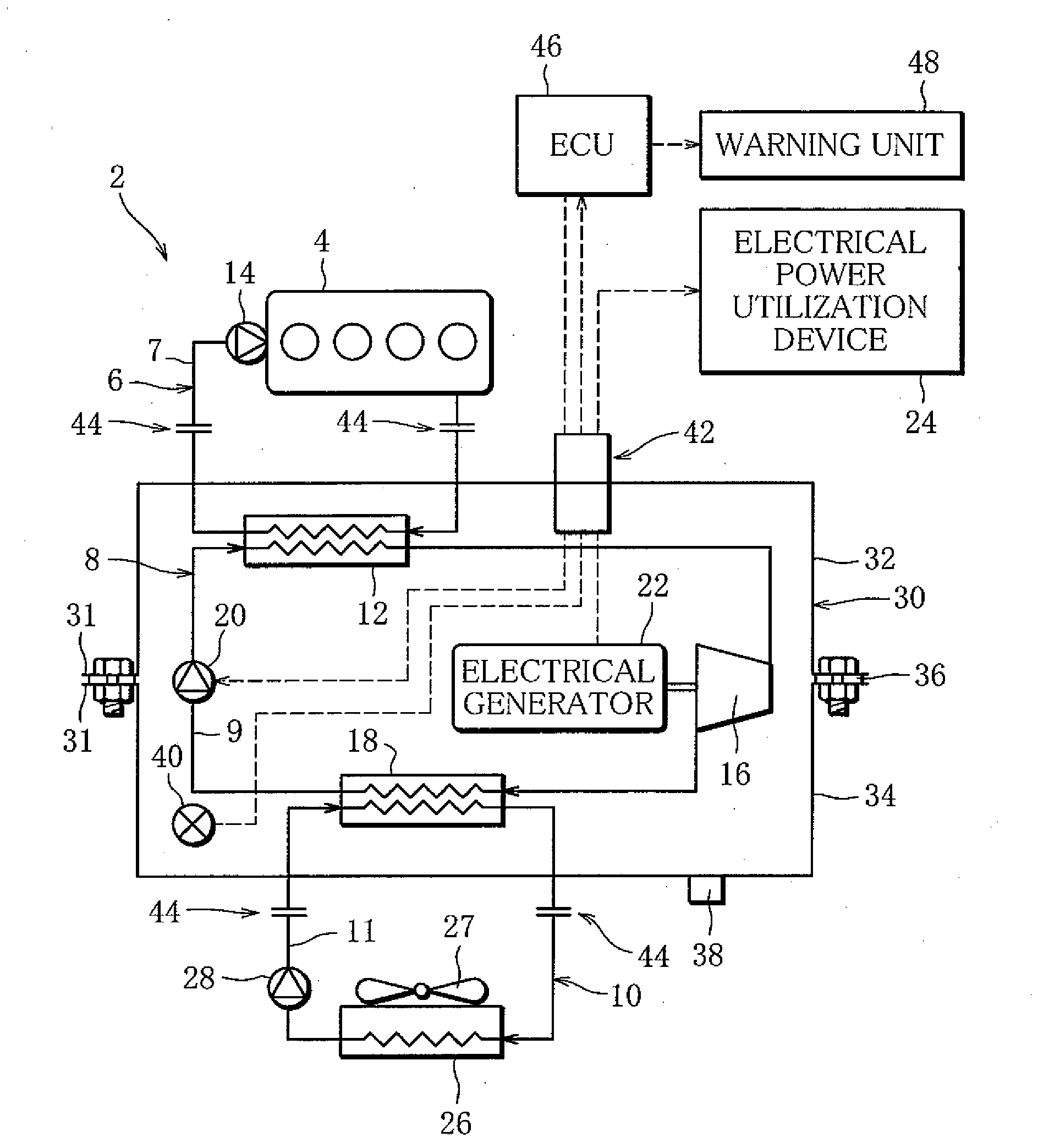
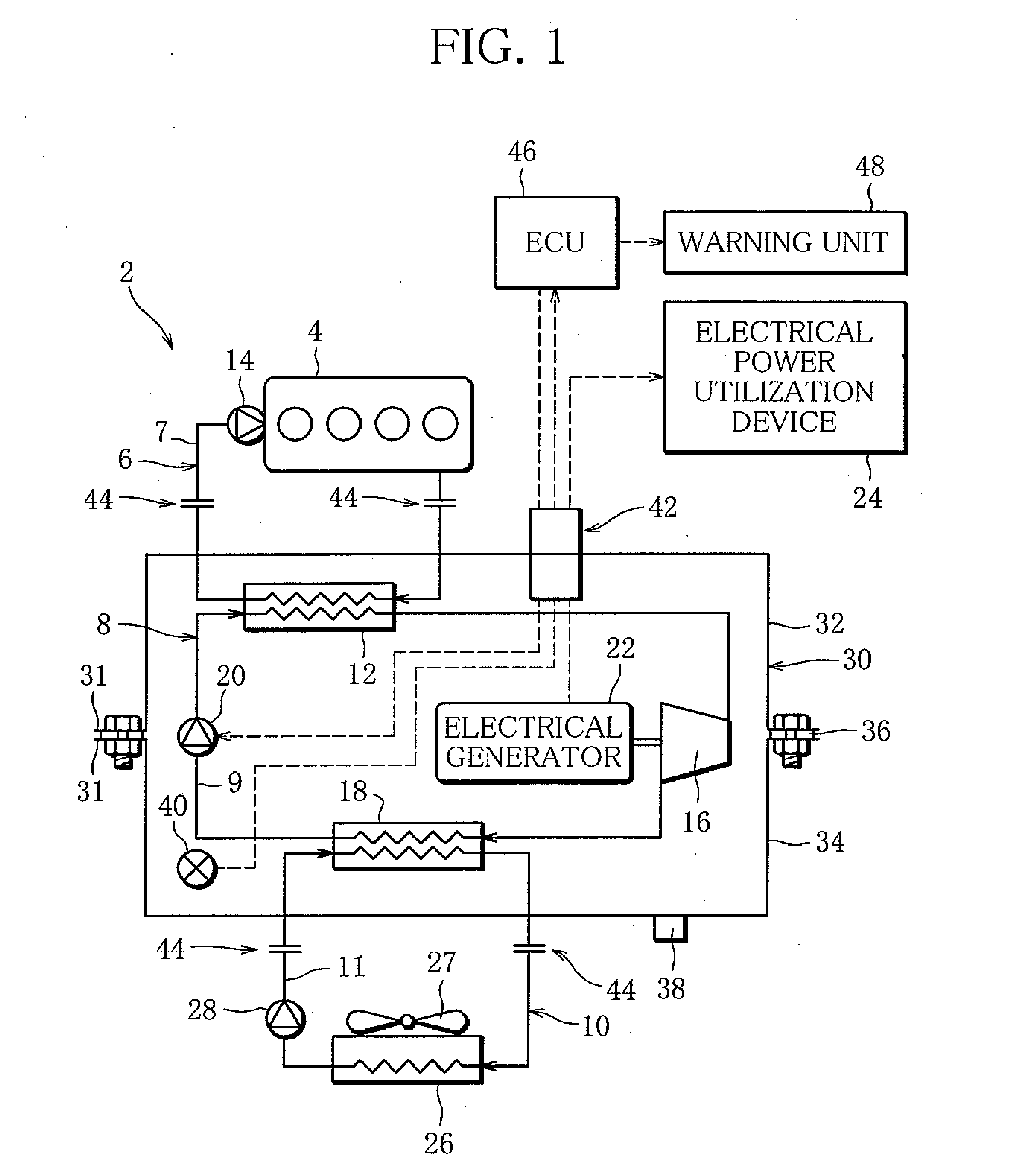
[0038]FIG. 1 is a schematic diagram showing a waste heat utilization device 2 for an internal combustion engine according to a first embodiment. The waste heat utilization device 2 comprises a first cooling water circuit 6 through which cooling water circulates, thereby cooling an automotive engine (internal combustion engine) 4, for example, a Rankine cycle circuit 8 (hereinafter referred to as “cycle 8”) through which a combustible hydrocarbon-based (HC) refrigerant circulates, thereby recovering waste heat produced by the engine 4, and a second cooling water circuit 10 through which cooling water circulates, thereby cooling the refrigerant.

[0039]The first cooling water circuit 6 constitutes a closed circuit including an evaporator 12 and a water pump 14 serially arranged in a circulation line 7 extending from the engine 4, where driving the water pump 14 causes the cooling water to circulate.

[0040]The evaporator 12 is a heat excha...

second embodiment

[0068]Next, a second embodiment will be described.

[0069]FIG. 4 shows a waste heat utilization device 50 according to a second embodiment. The waste heat utilization device 50 constitutes a third cooling water circuit 52 through cooling water circulates passing through the radiator 26 and the engine 4, where a three-way valve 54, a constituent of the third cooling water circuit 52, undergoes valve position control. In the other respects, this embodiment is similar to the first embodiment. Thus, the description will be given mainly of this difference.

[0070]The third cooling water circuit 52 is provided outside the casing 30, and constitutes a closed circuit including the three-way valve 54, the radiator 26, a check valve 56 and the water pump 14 serially arranged in a circulation line 53 extending from the engine 4, where driving the water pump 14 causes the cooling water to circulate passing through the engine 4 and then through the radiator 26. The section of the circulation line 53...


PUM


Abstract

A waste heat utilization device recovering waste heat produced by an internal combustion engine from a heat medium includes a Rankine cycle circuit including an evaporator, an expander, a condenser and a pump serially arranged in a circulation line along which a combustible working fluid circulates, a casing air-tightly enclosing the Rankine cycle circuit, and an inactivation device for creating a chemically-inactive condition inside the casing.

Description

TECHNICAL FIELD[0001]This invention relates to a waste heat utilization device for an internal combustion engine, specifically a waste heat utilization device for an internal combustion engine, suited to be mounted on a vehicle.BACKGROUND ART[0002]As a waste heat utilization device for an internal combustion engine, a cooling device for an automotive internal combustion engine is disclosed. This cooling device constitutes a Rankine cycle circuit including an evaporator, an expander and a condenser serially arranged in a circulation line along which CFC as a working fluid (hereinafter referred to as “refrigerant”) circulates, where heat is transferred from automotive engine cooling water to CFC in the evaporator. Drive power produced by the expander drives a radiator fan provided to the condenser, and CFC condensed in the condenser cools the engine (see Japanese Patent Application KOKAI Publication Sho 61-155614).[0003]At present, in order to prevent ozone layer depletion, alternativ...

Claims


Application Information

Patent Timeline
IPC IPC(8): F02G5/04F01K25/10
CPCF01K15/02F01K23/065F01K25/10F01P7/167F01P2005/105Y02T10/166F01P2060/14F02G5/00F02G5/04F02G2260/00F01P2031/18Y02T10/12
Inventor KASUYA, JUNICHIROKANOU, YASUAKI
Owner SANDEN CORP
Learn More