Oxyfuel Boiler and a Method of Controlling the Same
Active Publication Date: 2010-04-29
MITSUBISHI POWER LTD
3 Cites 42 Cited by
AI-Extracted Technical Summary
Problems solved by technology
For this reason, if concentration of oxygen supplied to the coal boiler is increased so that the heat storage quantity in the boiler satisfies the target value equivalent to that of an existing air fired boiler, the gas temperature in the furnace of the coal boiler also increase...
View moreBenefits of technology
[0032]According to the present invention, it is possible to reduce retrofit cost to convert a coal boiler operating as an existing air fired boiler to an oxyfuel boiler and prevent the oxyfuel boiler from deterio...
View moreAbstract
An oxyfuel boiler 1 is equipped with an oxygen separation apparatus 23 to produce oxygen by separating oxygen from the air, a recirculation fan 26 to supply a portion of combustion flue gas branched from the combustion flue gas discharged from the boiler to the oxyfuel boiler 1, a temperature sensor 14a to detect gas temperature at a boiler outlet 1d in the oxyfuel boiler 1, and a control apparatus 150 to calculate gas temperature at a furnace outlet 1c in the boiler from the gas temperature at the boiler outlet 1d detected by the temperature sensor 14a and control the operating condition of the recirculation fan 26 so that the calculated gas temperature at the furnace outlet 1c becomes a desired preset gas temperature.
Application Domain
Fluegas recirculationDirect carbon-dioxide mitigation +12
Technology Topic
Image
Examples
- Experimental program(1)
Example
Embodiment 1
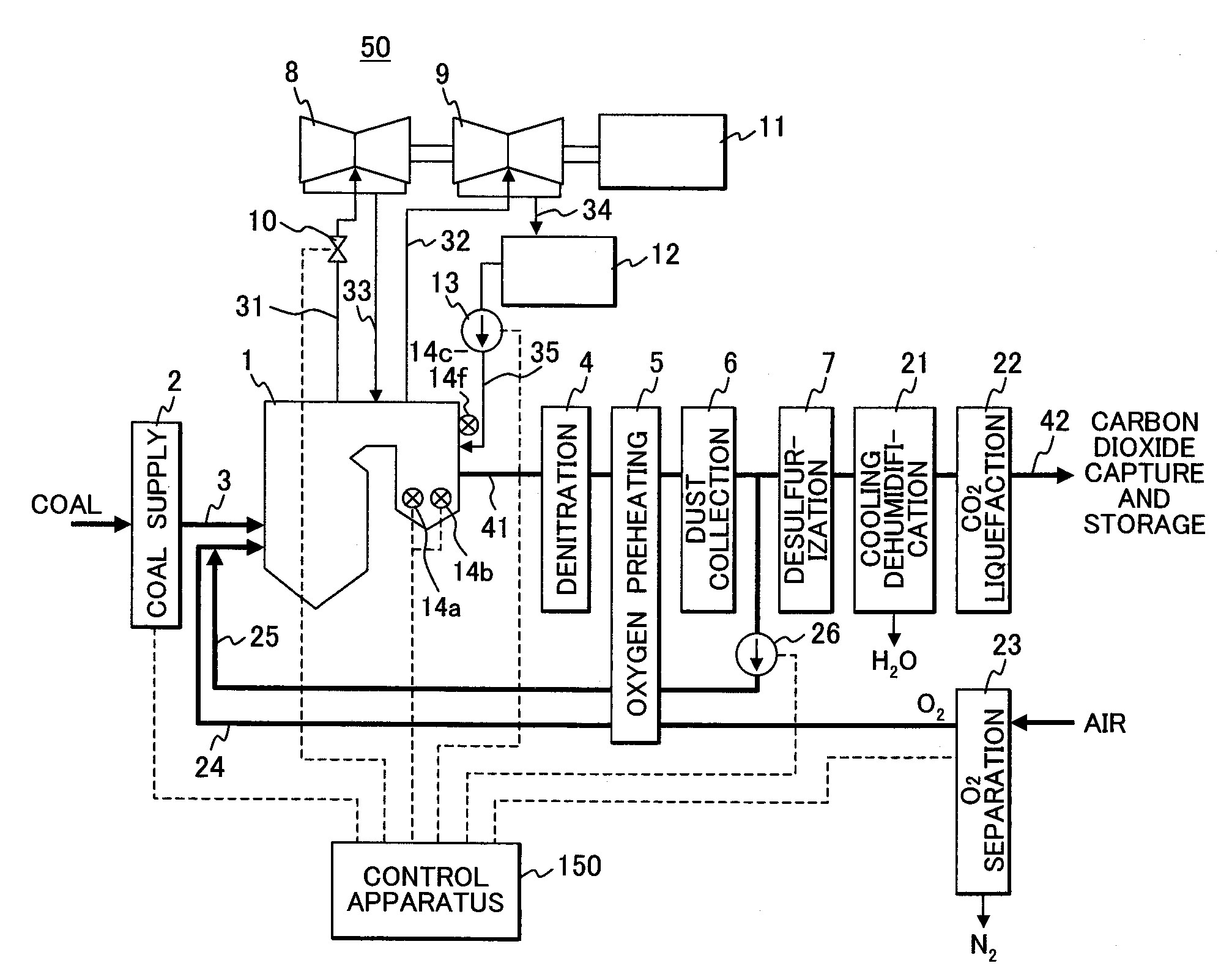
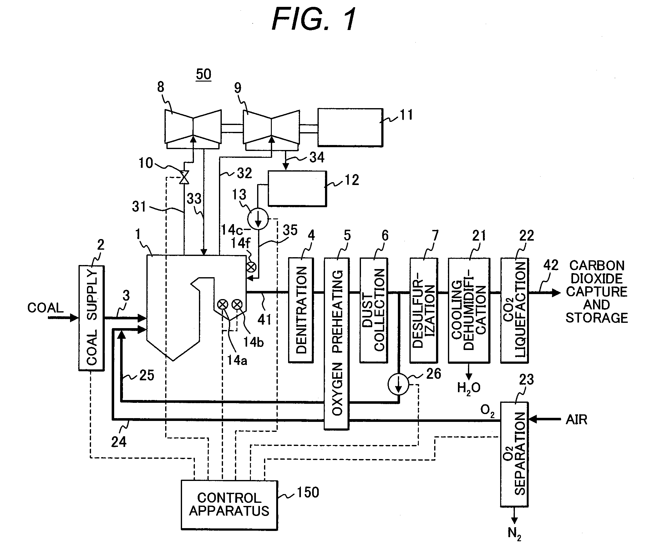
[0037]FIG. 1 is a schematic diagram showing the configuration of a coal thermal power plant suitable for the carbon dioxide capture and storage equipped with an oxyfuel boiler which is an embodiment of the present invention.
[0038]In FIG. 1, the coal thermal power plant is equipped with an oxyfuel boiler 1 having a furnace which uses powdered coal as a fuel and burns the powdered coal with oxygen separately supplied by a coal boiler. The structure of the oxyfuel boiler 1 is the same as that of an ordinary air fired boiler having a furnace which uses powdered coal as a fuel and burns the powdered coal with supplied air.
[0039]Fuel coal is pulverized to powdered coal by a coal supply apparatus 2, and the powdered coal is supplied from the coal supply apparatus 2 through a coal supply line 3 to the furnace of the oxyfuel boiler 1 and burned together with the separately supplied oxygen.
[0040]Combustion flue gas generated by burning powdered fuel coal with oxygen in the oxyfuel boiler 1 is introduced as combustion flue gas from the furnace of the oxyfuel boiler 1 through an combustion flue gas line 41 to a denitration apparatus 4 disposed downstream of the oxyfuel boiler 1, and the concentration of nitrogen oxide (NOx) contained in the combustion flue gas discharged from the oxyfuel boiler 1 is reduced to a desired value.
[0041]The combustion flue gas flowing down through the denitration apparatus 4 is introduced through the combustion flue gas line 41 to an oxygen preheater 5 disposed downstream of the denitration apparatus 4, and the oxygen preheater 5 uses the heat of the flowing-down combustion flue gas to heat the gas to be supplied to the oxyfuel boiler 1.
[0042]The combustion flue gas flowing down through the oxygen preheater 5 is introduced through the combustion flue gas line 41 to a dust collector 6 disposed downstream of the oxygen preheater 5, and the dust collector 6 removes powder dust contained in the combustion flue gas.
[0043]Further, the combustion flue gas flowing down through the dust collector 6 is introduced through the combustion flue gas line 41 to a desulfurization apparatus 7 disposed downstream of the dust collector 6, and the desulfurization apparatus 7 reduces the concentration of sulfur oxide (SOx) contained in the combustion flue gas to a desired value.
[0044]The oxyfuel boiler 1 is equipped with a plurality of heat exchangers (not shown) which are heated by combustion flue gas flowing down through the oxyfuel boiler 1, thereby generating steam.
[0045]Then, high-pressure, high-temperature steam generated in the heat exchangers of the oxyfuel boiler 1 is supplied from the oxyfuel boiler 1 passing through a steam line 31 to a high-pressure steam turbine 8 constructing a steam turbine unit 50 that is a steam demand equipment, thereby driving the high-pressure steam turbine 8. The flow volume of high-pressure steam supplied from the oxyfuel boiler 1 to the high-pressure steam turbine 8 is controlled by a control valve 10 provided in the steam line 31.
[0046]Steam discharged after driving the high-pressure steam turbine 8 is supplied through a steam line 33 to the heat exchangers disposed in the oxyfuel boiler 1, and low-pressure, high-temperature steam generated in the heat exchangers reheated by combustion flue gas flowing down through the oxyfuel boiler 1 is supplied from the oxyfuel boiler 1 through a steam line 32 to the low-pressure steam turbine 9 constructing the steam turbine unit 50, thereby driving the low-pressure steam turbine 9.
[0047]The steam turbine unit 50 is equipped with a generator 11 which rotates by the drive of the high-pressure steam turbine 8 and the low-pressure steam turbine 9, generating electric power. Then, steam discharged after driving the low-pressure steam turbine 9 is introduced through a steam line 34 to a condenser 12 and cooled to become condensed water.
[0048]Water condensed by the condenser 12 is pumped by a water supply pump 13 provided in the water supply line 35 and then supplied to heat exchangers, not shown, of the oxyfuel boiler 1 as supply water.
[0049]The oxyfuel boiler 1 is equipped with a temperature sensor 14a and an oxygen sensor 14b which measure the temperature of the combustion flue gas and the concentration of oxygen in the combustion flue gas, respectively. The coal thermal power plant equipped with the oxyfuel boiler 1 has a control apparatus 150 to perform various control operations.
[0050]Herein, in an actual coal thermal power plant, major devices other than the oxyfuel boiler also have various sensors for measuring state quantities, and the control apparatus 150 transmits control signals to operate the major devices based on the state quantities in the plant measured by various sensors disposed in the major devices constructing the coal thermal power plant. Thus, by this process, the coal thermal power plant operates.
[0051]FIG. 1 mainly shows the configuration related to the operation of the oxyfuel boiler 1 in the coal thermal power plant according to this embodiment, and other portions of the configuration are omitted.
[0052]Further, major devices constructing the above-mentioned coal thermal power plant are devices also provided in a coal thermal power plant equipped with an ordinary air fired boiler (the oxygen preheater 5 is called an air preheater in an ordinary coal thermal power plant because the preheater heats up air supplied to an air fired boiler).
[0053]In a coal thermal power plant equipped with an oxyfuel boiler 1 according to this embodiment, as shown in FIG. 1, a cooling and dehumidifying apparatus 21 which removes water by cooling flue gas flowing down through the desulfurization apparatus 7 is disposed in the combustion flue gas line 41 located on the downstream side of the desulfurization apparatus 7.
[0054]The combustion flue gas (mainly CO2) flowing down through the cooling and dehumidifying apparatus 21 and passing through the dust removal, denitration, desulfurization and dehumidification processes is introduced through the combustion flue gas line 41 to a carbon dioxide liquefaction unit 22 disposed downstream of the cooling and dehumidifying apparatus 21, and then CO2 contained in the combustion flue gas is separated, compressed and liquefied in the carbon dioxide liquefaction unit 22.
[0055]Liquefied CO2 compressed and liquefied by the carbon dioxide liquefaction unit 22 is sent from the carbon dioxide liquefaction unit 22 through a carbon dioxide capture and storage line 42 to a storage facility, not shown, and is stored therein.
[0056]There is provided an oxygen separation apparatus 23 which separates oxygen (O2) and nitrogen (N2) from air taken from the atmosphere. Oxygen separated by the oxygen separation apparatus 23 is supplied through an oxygen supply line 24 to the oxyfuel boiler 1, mixed with recirculating combustion flue gas to form as an oxidizing gas, and the oxidizing gas burns powdered coal supplied from the coal supply line 3 in the oxyfuel boiler 1.
[0057]The oxygen supply line 24 is designed to supply pure oxygen separated by the oxygen separation apparatus 23 or oxygen (which contains a trace of nitrogen and the like as impurities) through an oxygen preheater 5 to the oxyfuel boiler 1. Therefore, the pure oxygen or oxygen is preheated in the oxygen preheater 5 by the combustion flue gas flowing down through the combustion flue gas line 41, subsequently supplied through the oxygen supply line 24 to the oxyfuel boiler 1, and used to burn the powdered coal. Furthermore, after oxygen has been separated from air by the oxygen separation apparatus 23, the remaining gas (mainly N2) is discharged outside of the line.
[0058]In a coal thermal power plant equipped with an oxyfuel boiler according to this embodiment, there is provided a recirculation line 25 which branches from the combustion flue gas line 41 between the dust collector 6 and the desulfurization apparatus 7, introduces a portion of combustion flue gas, and recirculates the combustion flue gas in the oxyfuel boiler 1.
[0059]The recirculation line 25 is equipped with a recirculation fan 26 which is designed to transport a portion of the combustion flue gas branched from the combustion flue gas line 41 to the oxyfuel boiler 1 to be used as the recirculating flue gas. Because the recirculation line 25 is designed to supply the recirculating combustion flue gas through the oxygen preheater 5 to the oxyfuel boiler 1, the recirculating combustion flue gas is heated by the combustion flue gas flowing down through the combustion flue gas line 41 in the oxygen preheater 5, subsequently supplied through the recirculation line 25 to the oxyfuel boiler 1, mixed with oxygen supplied through the oxygen supply line 24 to form oxidizing gas, and the oxidizing gas burns powdered coal supplied by the coal supply line 3 in the oxyfuel boiler 1.
[0060]As stated above, the oxidizing gas supplied to the oxyfuel boiler 1 is a mixture of pure oxygen supplied from the oxygen supply line 24 and recirculating combustion flue gas supplied through the recirculation line 25.
[0061]In the control apparatus 15, the amount of pure oxygen supply is regulated by controlling the operation of the oxygen separation apparatus 23 according to the command signal calculated by the control apparatus 15, while the amount of circulating flue gas is regulated by controlling the number of revolutions of the recirculation fan 26 according to the command signal calculated by the control apparatus 15. Thus, control is performed so that concentration of oxygen contained in the oxidizing gas, which is a mixture of pure oxygen and circulating combustion flue gas, becomes a desired value.
[0062]The amount of oxidizing gas supplied to the oxyfuel boiler 1 is the sum of the amount of pure oxygen supply and the amount of circulating combustion flue gas. Further, oxygen contained in the oxidizing gas is a mixture of oxygen supplied from the oxygen separation apparatus 23 and a trace of oxygen remaining in the circulating combustion flue gas, and supplied to the oxyfuel boiler 1.
[0063]Concentration of oxygen in the oxidizing gas supplied to the oxyfuel boiler 1 can be increased by increasing the amount of pure oxygen supply by controlling the operation of the oxygen separation apparatus 23 or decreasing the amount of circulating combustion flue gas by controlling the number of revolutions of the recirculation fan 26.
[0064]On the other hand, the quantity of fuel coal supplied to the oxyfuel boiler 1 can be adjusted by controlling the operation of the coal supply apparatus 2.
[0065]The above-mentioned control means adjusts the amount of oxygen supply, amount of circulating combustion flue gas, and the amount of coal supply which are parameters for controlling the combustion condition in the oxyfuel boiler 1.
[0066]In a coal thermal power plant equipped with an oxyfuel boiler according to this embodiment, concentration of oxygen contained in the oxidizing gas supplied to the oxyfuel boiler 1 is controlled by the use of gas temperature in the oxyfuel boiler 1, for example, gas temperature at a furnace outlet 1c of the oxyfuel boiler 1 as a reference to determine the concentration of oxygen contained in the oxidizing gas.
[0067]In most cases, gas at the furnace outlet 1c of the oxyfuel boiler 1 is too hot for a temperature sensor to be disposed. For this reason, gas temperature at the furnace outlet 1c is calculated according to thermal balance based on an actual value measured by a temperature sensor disposed in a different location.
[0068]In a coal thermal power plant equipped with an oxyfuel boiler according to this embodiment, in the oxyfuel boiler 1 which burns powdered coal, the furnace outlet 1c is located in the boundary 201 between the furnace 1a and the rear heat transfer surface 1b, as shown in FIG. 2, and the upstream side of the boundary 201 is called a furnace la and the downstream side is called a rear heat transfer surface 1b.
[0069]A combustion burner 101 is disposed at the lower portion of the furnace 1a shown in FIG. 2, and powdered coal supplied from the combustion burner 101 is burned with oxidizing gas which is a mixture of oxygen and recirculating combustion flue gas, thereby generating high-temperature combustion gas.
[0070]Structurally, high-temperature combustion gas flows down through the furnace 1a toward the boiler outlet 1d while transferring heat to steam which flows through a plurality of heat exchangers made up of water tubes provided in the oxyfuel boiler 1.
[0071]A water tube called a spiral tube 102 is disposed spirally on the lower wall surface of the furnace la, while a water tube called an open-path tube 103 is disposed vertically on the upper wall surface of the furnace la. The spiral tube 102 and the open-path tube 103 are collectively referred to as a water wall.
[0072]Further, a water tube 104 called a cage wall is disposed on the wall surface on the rear heat transfer surface 1b side shown in FIG. 2. The water wall and the cage wall are water tubes located on the wall surface, while a plurality of heat exchangers made up of water tubes are located inside the oxyfuel boiler 1.
[0073]Among those heat exchangers, a secondary superheater 111 is suspended from the ceiling of the furnace la. Further, on the downstream side of the secondary superheater 111, heat exchangers of tertiary superheater 112, reheater 113, primary superheater 114, and economizer 115 are sequentially disposed along the direction of the combustion gas flow.
[0074]In a coal thermal power plant equipped with an oxyfuel boiler 1 according to this embodiment, the reason why the balance of the heat absorption quantity in the above-mentioned heat exchangers changes as the result of adjustments to the concentration of oxygen contained in the oxidizing gas, which is a mixture of pure oxygen supplied from the oxygen supply line 24 to the oxyfuel boiler 1 and recirculating combustion flue gas supplied through the recirculation line 25, is that forms of heat transfer, such as convection heat transfer and radiation heat transfer, are related.
[0075]Convection heat transfer is a phenomenon in which heat transfers on the contact surface between high-temperature combustion gas and a water tube due to a temperature difference therebetween. On the other hand, radiation heat transfer is a phenomenon in which electromagnetic waves generated from high-temperature combustion gas are absorbed by a water tube and then converted to thermal energy, and thus, heat is transferred.
[0076]Both the convection heat transfer and the radiation heat transfer always act on the heat transfer from the combustion gas in the boiler to the heat exchangers. In areas such as in the furnace 1a where the temperature of combustion gas is high, radiation heat transfer becomes dominant, and in areas such as on the rear heat transfer surface 1b where the temperature of combustion gas is comparatively low, convection heat transfer becomes dominant. This is attributed to a physical property of the radiation heat transfer quantity being proportional to the fourth power of gas temperature.
[0077]For this reason, in an oxyfuel boiler 1, if concentration of oxygen contained in the oxidizing gas is increased by reducing the amount of circulating combustion flue gas supplied through the recirculation line 25 to the oxyfuel boiler 1, flame temperature in the furnace la increases, which increases the radiation heat transfer quantity in the furnace 1a as well as increases the amount of heat absorption on the furnace 1a side.
[0078]On the other hand, when the amount of circulating combustion flue gas supplied through the recirculation line 25 to the oxyfuel boiler 1 decreases, the volume of the gas flowing through the oxyfuel boiler 1 decreases, causing the velocity of the gas flow to decrease. At this point in time, the above-mentioned convection heat transfer has a physical property of the heat transfer quantity decreasing with the decrease in the velocity of gas flow.
[0079]Therefore, if concentration of oxygen contained in the oxidizing gas is increased by reducing the amount of circulating combustion flue gas supplied through the recirculation line 25 to the oxyfuel boiler 1, the amount of heat absorption decreases on the rear heat transfer surface 1b where the convection heat transfer is dominant.
[0080]That is, in the oxyfuel boiler 1, if concentration of oxygen contained in the oxidizing gas is increased by reducing the amount of circulating combustion flue gas supplied to the oxyfuel boiler 1, the amount of heat absorption increases on the furnace 1a side where the radiation heat transfer is dominant, while the amount of heat absorption decreases on the rear heat transfer surface 1b side where the convection heat transfer is dominant.
[0081]Further, if concentration of oxygen contained in the oxidizing gas is decreased by increasing the amount of circulating combustion flue gas supplied to the oxyfuel boiler 1, the above action will occur in reverse.
[0082]According to the above-mentioned phenomena, it is possible to change the balance of the heat absorption quantity in the heat exchangers disposed in the oxyfuel boiler 1 by adjusting the concentration of oxygen contained in the oxidizing gas supplied to the oxyfuel boiler 1.
[0083]Further, in the case of a general air fired boiler, the overall heat storage quantity in the boiler which joins the furnace 1a side and the rear heat transfer surface 1b side tends to increase by decreasing the amount of circulating combustion flue gas and simultaneously increasing the oxygen concentration. This is because heat transfer efficiency increases as the gas temperature increases.
[0084]When retrofitting an existing air fired boiler which burns powdered coal with air to an oxyfuel boiler 1 which burns powdered coal with oxygen, in terms of retrofit cost, it is preferable that the balance of the heat absorption quantity in each heat exchanger in oxygen combustion be equivalent to that in air combustion. This is because material for heat exchangers is selected at the boiler design stage on the basis of the balance of the heat absorption quantity in each heat exchanger (steam temperature and pressure in a water tube, and gas temperature outside the water tube).
[0085]In a heat exchanger installed in a boiler, expensive highly heat-resistant material is used in areas of high temperature and inexpensive moderately heat-resistant material is used in areas of comparatively low temperature. For this reason, if the heat absorption balance in oxygen combustion significantly changes from that in air combustion by retrofitting an existing air fired boiler to an oxyfuel boiler, the conditions also change, such as temperature and the like, which are the criteria of selection of material at the design stage. Therefore, it is expected that the boiler cannot be operated as it is in terms of heat resistance of the material.
[0086]To cope with such situations, there is an idea of retrofitting each heat exchanger (specifically, addition or deletion of a water tube) provided in the oxyfuel boiler 1 to change the area of heat transfer so that the temperature will become lower than the material's service temperature limit. However, this retrofit presumably requires a considerable amount of cost.
[0087]Therefore, in the oxyfuel boiler 1 according to this embodiment provided in a coal thermal power plant, the gas temperature in the oxyfuel boiler 1, which is the gas temperature at a furnace outlet 1c located in the boundary 201 between the furnace 1a and the rear heat transfer surface 1b in FIG. 2, is used as a reference temperature to determine the concentration of oxygen contained in the oxidizing gas supplied to the oxyfuel boiler 1.
[0088]Since gas temperature at the furnace outlet 1c is significantly high, it is difficult to directly measure the gas temperature by installing a temperature sensor at the furnace outlet 1c. Therefore, in the control apparatus 150 of the oxyfuel boiler according to this embodiment, as shown in FIG. 2 and FIG. 3, a temperature sensor 14a and a gas composition sensor 14b are provided at a boiler outlet 1d where gas temperature is lower than that at the furnace outlet 1c, and gas temperature and gas composition are measured, respectively, at the boiler outlet 1d where measurement is possible.
[0089]As shown in FIG. 3, a boiler-outlet gas calorie computing unit 151 for calculating gas calorie at the boiler outlet 1d is provided in the control apparatus 150 for controlling the oxyfuel boiler 1 according to this embodiment. This boiler-outlet gas calorie computing unit 151 calculates gas calorie at the boiler outlet 1d based on the gas temperature and gas composition measured by the temperature sensor 14a and the gas composition sensor 14b, respectively, located at the boiler outlet 1d.
[0090]That is, because the boiler-outlet gas calorie computing unit 151 has computing functions for calculating Equation (1) and Equation (2), Equation (1) and Equation (2) are calculated by the computing functions of the boiler-outlet gas calorie computing unit 151 based on the gas temperature and gas composition measured by the temperature sensor 14a and the gas composition sensor 14b, respectively, located at the boiler outlet 1d, thereby calculating gas calorie at the boiler outlet 1d.
[Equation 1]
Hg2,i=fi(Tg2) (1)
[0091]In Equation (1),
[0092]Hg2,i represents gas enthalpy of substance i at the boiler outlet,
[0093]fi( ) represents a temperature-enthalpy conversion function of substance i in the gas, and
[0094]Tg2 represents gas temperature at the boiler outlet.
[ Equation 2 ] Q g 2 = F g × ∑ i ( w i × H g 2 , i ) ( 2 )
[0095]In Equation (2),
[0096]Qg2 represents gas calorie at the boiler outlet,
[0097]Fg represents gas flow volume,
[0098]Wi represents a mass ratio of substance i in the gas, and
[0099]Hg2,i represents gas enthalpy of substance i at the boiler outlet.
[0100]Then, by the calculations using the Equation (1) computing function and the Equation (2) computing function provided in the boiler-outlet gas calorie computing unit 151, gas enthalpy of each substance i (for example, carbon dioxide, oxygen, nitrogen, or water) is obtained from the gas temperature measured by the temperature sensor 14a, thereby calculating gas calorie at the boiler outlet. The temperature-enthalpy conversion function of each substance uses known data conditional on atmospheric pressure. Further, gas composition (weight ratio of each substance contained in the gas) uses a value measured by the gas composition sensor 14b.
[0101]The control apparatus 150 is equipped with a heat-exchanger total calorie computing unit 152 to calculate calorie obtained by heat exchangers (cage wall 104, tertiary superheater 112, reheater 113, primary superheater 114, economizer 115, and cage wall 104) located between the furnace outlet and the boiler outlet in the oxyfuel boiler 1 as well as calculate the sum of the calorie.
[0102]The heat-exchanger total calorie computing unit 152 provided in the control apparatus 150 has an Equation (3) computing function for calculating total calorie obtained by steam in the heat exchangers. Therefore, Equation (3) is calculated by the computing function of the heat-exchanger total calorie computing unit 152 based on each value of the inlet steam temperature, outlet steam temperature, steam pressure and steam flow volume measured by an inlet temperature sensor 14c, outlet temperature sensor 14d, pressure sensor 14e, and a flow volume sensor 14f, respectively, located in each heat exchanger, thereby calculating total calorie obtained by steam in the heat exchangers.
[ Equation 3 ] Q w = ∑ j F w , j × ( H wout , j - H win , j ) ( 3 )
[0103]In Equation (3),
[0104]QW represents calorie obtained by heat exchangers located between the furnace outlet and the boiler outlet,
[0105]Fw,j represents steam flow volume of heat exchanger j,
[0106]Hwout,j represents outlet steam enthalpy of heat exchanger j, and
[0107]Hwin,j represents inlet steam enthalpy of heat exchanger j.
[0108]Then, total calorie obtained by the heat exchangers located between the furnace outlet and the boiler outlet is calculated by the Equation (3) computing function provided in the heat-exchanger total calorie computing unit 152.
[0109]Enthalpy of steam is obtained by converting measured values of steam temperature and steam pressure to enthalpy according to the steam table.
[0110]The control apparatus 150 is equipped with a furnace-outlet gas calorie computing unit 153 for calculating gas calorie at the furnace outlet 1c based on the total calorie obtained by steam in the heat exchangers calculated by the heat-exchanger total calorie computing unit 152.
[0111]The furnace-outlet gas calorie computing unit 153 has an Equation (4) computing function. Therefore, Equation (4) is calculated by the computing function of the furnace-outlet gas calorie computing unit 153 based on the total calorie obtained by heat exchangers calculated by the heat-exchanger total calorie computing unit 152, thereby calculating gas calorie at the furnace outlet 1c.
[Equation 4]
Qg1=Qg2+Qw (4)
[0112]In Equation (4),
[0113]Qg1 represents gas calorie at the furnace outlet,
[0114]Qg2 represents gas calorie at the boiler outlet, and
[0115]QW represents calorie obtained by heat exchangers located between the furnace outlet and the boiler outlet.
[0116]With regard to gas calorie at the boiler outlet 1d, gas calorie at the furnace outlet 1c can be judged as the total calorie obtained by steam through heat exchangers. Herein, calculation target heat exchangers are those located between the furnace outlet 1c and the boiler outlet 1d.
[0117]Then, gas calorie at the furnace outlet 1c is calculated using an Equation (4) computing function provided in the furnace-outlet gas calorie computing unit 153.
[0118]The control apparatus 150 is further equipped with a furnace-outlet gas temperature computing unit 154 for calculating gas temperature at the furnace outlet 1c based on the gas calorie at the furnace outlet 1c calculated by the furnace-outlet gas calorie computing unit 153.
[0119]The furnace-outlet gas temperature computing unit 154 has Equation (5) and Equation (6) computing functions. Therefore, Equation (5) and Equation (6) are calculated by the computing functions of the furnace-outlet gas temperature computing unit 154 based on the gas calorie at the furnace outlet 1c calculated by the furnace-outlet gas calorie computing unit 153, thereby calculating gas temperature at the furnace outlet 1c.
[Equation 5]
Hg1,i=fi(Tg1) (5)
[0120]In Equation (5),
[0121]Hg1,i represents gas enthalpy of substance i at the furnace outlet,
[0122]fi( ) represents a temperature-enthalpy conversion function of substance i in the gas, and
[0123]Tg1 represents gas temperature at the furnace outlet.
[ Equation 6 ] Q g 1 = F g × ∑ i ( w i × H g 1 , i ) ( 6 )
[0124]In Equation (6),
[0125]Qg1 represents gas calorie at the furnace outlet,
[0126]Fg represents gas flow volume,
[0127]Wi represents a mass ratio of substance i in the gas, and
[0128]Hg1,i represents gas enthalpy of substance i at the furnace outlet.
[0129]When calculating gas temperature at the furnace outlet 1c using Equation (5) and Equation (6) computing functions provided in the furnace-outlet gas temperature computing unit 154, gas temperature at the furnace outlet 1c is calculated after gas calorie at the furnace outlet 1c has been calculated. At the beginning, gas calorie at the furnace outlet 1c is calculated by providing an initial value as the gas temperature at the furnace outlet 1c, then comparison is made between the calculated gas calorie and the gas calorie at the furnace outlet 1c calculated by Equation (4), and while gas temperature is updated, gas temperature at the furnace outlet 1c is obtained by convergence calculation.
[0130]Herein, state quantities of the oxyfuel boiler 1 necessary for calculating gas temperature at the furnace outlet 1c are, as stated above, values measured by the temperature sensor 14a and the gas composition sensor 14b disposed at the boiler outlet 1d.
[0131]The control apparatus 150 is equipped with a temperature setter 155 for setting a desired gas temperature at the furnace outlet 1d. The control apparatus 150 is further equipped with a comparison computing unit 156 for comparing the gas temperature at the furnace outlet 1c calculated by the furnace-outlet gas temperature computing unit 154 with a preset gas temperature set by the temperature setter 155 and adjusting the recirculation fan 26 drive condition according to the command signal based on the deviation signal between those two temperature values. Thus, the comparison computing unit 156 is designed to control the amount of circulating combustion flue gas supplied from the recirculation fan 26 to the oxyfuel boiler 1.
[0132]Furthermore, the control apparatus 150 is equipped with a boiler-outlet oxygen concentration measuring instrument 157 for detecting oxygen concentration at the boiler outlet 1d from an flue gas composition value at the boiler outlet 1d measured by the gas composition sensor 14b disposed at the boiler outlet 1d, and the control apparatus 150 is also equipped with an oxygen concentration setter 158 for setting a desired oxygen concentration in the combustion flue gas at the furnace outlet 1d.
[0133]The control apparatus 150 is further equipped with a comparison computing unit 159 for comparing the calculated oxygen concentration at the boiler outlet 1d detected by the boiler-outlet oxygen concentration measuring instrument 157 with a preset oxygen concentration set by the oxygen concentration setter 158 and adjusting the operating condition of the oxygen supply apparatus 23 by the command signal based on the deviation signal between those two oxygen concentration values. Thus, the comparison computing unit 159 is designed to control volume of oxygen flow supplied from the oxygen supply apparatus 23 to the oxyfuel boiler 1.
[0134]Next, control of gas temperature at the furnace outlet by an oxyfuel boiler 1 according to this embodiment will be explained below.
[0135]The control apparatus 150 provided in the oxyfuel boiler 1 according to this embodiment, shown FIG. 1 through FIG. 3, controls gas temperature at the furnace outlet 1c as described below.
[0136]First, gas calorie at the boiler outlet 1d is calculated by the boiler-outlet gas calorie computing unit 151 provided in the control apparatus 150 based on the gas temperature at the boiler outlet measured by the temperature sensor 14a provided at the boiler outlet 1d and a value measured by the gas composition sensor 14b.
[0137]Next, total calorie obtained by the heat exchangers is calculated by the heat-exchanger total calorie computing unit 152 based on a value calculated by the boiler-outlet gas calorie computing unit 151 and the state quantities measured in the heat exchangers.
[0138]Next, gas calorie at the furnace outlet 1d is calculated by the furnace-outlet gas calorie computing unit 153 based on the value calculated by the heat-exchanger total calorie computing unit 152, and then, gas temperature at the furnace outlet 1c is calculated by the furnace-outlet gas temperature computing unit 154 based on the value calculated by the furnace-outlet gas calorie computing unit 153.
[0139]Then, the comparison computing unit 156 compares gas temperature at the furnace outlet 1c calculated by the furnace-outlet gas temperature computing unit 154 with the preset temperature set by the temperature setter 155, and if the gas temperature at the furnace outlet 1c calculated by the furnace-outlet gas temperature computing unit 154 is lower than the preset temperature set by the temperature setter 155, the command signal based on the deviation signal compared by the comparison computing unit 156 operates to reduce the drive of the recirculation fan 26 which supplies flue gas to the oxyfuel boiler 1. Thus, the amount of recirculating combustion flue gas is decreased and concentration of oxygen contained in the oxidizing gas supplied to the oxyfuel boiler 1 is increased, consequently, the gas temperature at the furnace outlet 1c is controlled to become a desired temperature.
[0140]Further, as the result of comparison by the comparison computing unit 156, if gas temperature at the furnace outlet 1c calculated by the furnace-outlet gas temperature computing unit 154 is higher than the preset temperature set by the temperature setter 155, the command signal based on the deviation signal compared by the comparison computing unit 156 operates to enhance the drive of the recirculation fan 26 which supplies combustion flue gas to the oxyfuel boiler 1. Thus, the amount of recirculating combustion flue gas is increased and concentration of oxygen contained in the oxidizing gas supplied to the oxyfuel boiler 1 is decreased, consequently, the gas temperature at the furnace outlet 1c is controlled to become a desired temperature.
[0141]Next, complementary control of oxygen concentration at a boiler outlet of the oxyfuel boiler according to this embodiment will be explained below.
[0142]The control apparatus 150 provided in the oxyfuel boiler 1 according to this embodiment, shown in FIG. 1 through FIG. 3, complementarily controls oxygen concentration at the furnace outlet 1d as described below.
[0143]Oxygen concentration at the boiler outlet 1d is detected by the boiler-outlet oxygen concentration measuring instrument 157 provided in the control apparatus 150 based on the value measured by the gas composition sensor 14b provided at the boiler outlet 1d.
[0144]Then, the comparison computing unit 159 compares the oxygen concentration at the boiler outlet 1d detected by the oxygen concentration measuring instrument 157 with the preset oxygen concentration value set by the oxygen concentration setter 158, and if actual oxygen concentration at the boiler outlet 1d detected by the oxygen concentration measuring instrument 157 is lower than the preset oxygen concentration set by the oxygen concentration setter 158, the command signal based on the deviation signal compared by the comparison computing unit 159 operates to increase the operation of the oxygen supply apparatus 23. Thus, the oxygen quantity supplied from the oxygen supply apparatus 23 to the oxyfuel boiler 1 is increased, and the oxygen concentration at the boiler outlet 1d is controlled to become a predetermined concentration.
[0145]Further, as the result of comparison by the comparison computing unit 159, if actual oxygen concentration at the boiler outlet 1d detected by the oxygen concentration measuring instrument 157 is higher than the preset oxygen concentration set by the oxygen concentration setter 158, the command signal based on the deviation signal compared by the comparison computing unit 159 operates to reduce the operation of the oxygen supply apparatus 23. Thus, the oxygen quantity supplied from the oxygen supply apparatus 23 to the oxyfuel boiler 1 is decreased, and the oxygen concentration at the boiler outlet 1d is controlled to become a predetermined concentration.
[0146]According to the above-mentioned embodiment of the present invention, it is possible to reduce retrofit cost to convert a coal boiler operating as an existing air fired boiler to an oxyfuel boiler and prevent the oxyfuel boiler from deteriorating or slagging due to high-temperature gas, and consequently, a highly reliable oxyfuel boiler which can stably operate for a long period of time and a method of controlling the oxyfuel boiler can be achieved.
INDUSTRIAL APPLICABILITY
[0147]The present invention can be applied to an oxyfuel boiler and a method of controlling the oxyfuel boiler suitable for the carbon dioxide capture and storage in a coal thermal power plant.
Login to view more PUM


Description & Claims & Application Information
We can also present the details of the Description, Claims and Application information to help users get a comprehensive understanding of the technical details of the patent, such as background art, summary of invention, brief description of drawings, description of embodiments, and other original content. On the other hand, users can also determine the specific scope of protection of the technology through the list of claims; as well as understand the changes in the life cycle of the technology with the presentation of the patent timeline. Login to view more.
Login to view more Similar technology patents
Semiconductor memory device and refresh period controlling method
InactiveUS20050281112A1Improved temperature compensationCost reductionError detection/correctionCode conversionError ratioRate measurement
Owner:PS4 LUXCO SARL
Versatile orthopaedic leg mounted walkers
ActiveUS7303538B2Cost reductionIncreased surface contact and grip actionWalking aidsNon-surgical orthopedic devicesPlastic surgeryMechanical engineering
Owner:OSSUR HF
Accelerometer to monitor movement of a tool assembly attached to a robot end effector
InactiveUS20060178775A1Cost reductionProgramme controlProgramme-controlled manipulatorRobot end effectorMetallic Lead
Owner:ABB RES LTD
Method and apparatus for temperature, conductance and/or impedance testing in remote application of battery monitoring systems
InactiveUS20070046261A1Improved installation maintenance reliabilityCost reductionBatteries circuit arrangementsElectrical testingPeripheralEngineering
Owner:ENERSAFE
System and method for providing receipts, advertising, promotion, loyalty programs, and contests to a consumer via an application-specific user interface on a personal communication device
ActiveUS20080308628A1Cost reductionLiquid transferring devicesApparatus for dispensing fluids/granular materialsProgram planningLoyalty program
Owner:GILBARCO
Classification and recommendation of technical efficacy words
- Cost reduction
- High reliability
Floorboards, flooring systems and methods for manufacturing and installation thereof
ActiveUS20040139678A1Increase wear resistanceCost reductionStrutsWallsMechanical engineeringFloating floor
Owner:VÄLINGE INNOVATION AB
System apparatus and method for hosting and assigning domain names on a wide area network
InactiveUS6687746B1Eliminate costCost reductionData processing applicationsDigital data processing detailsManagement systemData mining
Owner:FAR NORTH PATENTS LLC
Controlling method and system for RGB based LED luminary
InactiveUS6507159B2Cost reductionHigh rippleStatic indicating devicesElectroluminescent light sourcesEngineeringForward current
Owner:SIGNIFY HLDG BV
Reconfigurable platform management apparatus for virtual reality-based training simulator
InactiveUS20120122062A1Cost reductionReduce riskEducational modelsSimulatorsDriving simulatorTraining simulation
Owner:ELECTRONICS & TELECOMM RES INST
Plasma enhanced vapor phase deposition
InactiveUS20150147488A1Excellent step coverageHigh reliabilityChemical vapor deposition coatingPlasma techniqueIonVapor phase
Owner:SK HYNIX INC +1
Light-Emitting Device, Lighting Device, and Electronic Device
ActiveUS20110001146A1High reliabilityElectroluminescent light sourcesSolid-state devicesMetal substrateEngineering
Owner:SEMICON ENERGY LAB CO LTD
Methods and system to quantify depth data accuracy in three-dimensional sensors using single frame capture
InactiveUS20060197937A1High reliabilityOptical rangefindersElectromagnetic wave reradiationPhase shiftedLow Confidence
Owner:MICROSOFT TECH LICENSING LLC
Multi-series battery control system
ActiveUS20050242667A1High reliabilityCharge equalisation circuitCircuit monitoring/indicationControl systemControl circuit
Owner:HITACHI ASTEMO LTD