Liquid cooling apparatus and method for cooling blades of an electronic system chassis

Inactive Publication Date: 2010-04-29
BRAINSCOPE SPV LLC +1
View PDF99 Cites 104 Cited by
  • Summary
  • Abstract
  • Description
  • Claims
  • Application Information

AI Technical Summary

Benefits of technology

[0005]The shortcomings of the prior art are overcome and additional advantages are provided through the provision of a liquid cooling apparatus for at least one electronic system chassis. The liquid cooling apparatus includes at least one chassis-level manifold assembly, wherein each chassis-level manifold assembly is configured to couple to a respective electronic system chassis of the at least one electronic system chassis. Each chassis-level manifold assembly includes a first coolant path and a plurality of second coolant paths, wherein the first coolant path is isolated from the plurality of second coolant paths by a heat exchanger. Th

Problems solved by technology

This trend poses a cooling challenge at both the module and system lev

Method used


Image

  • Liquid cooling apparatus and method for cooling blades of an electronic system chassis
  • Liquid cooling apparatus and method for cooling blades of an electronic system chassis
  • Liquid cooling apparatus and method for cooling blades of an electronic system chassis

Examples


Embodiment Construction

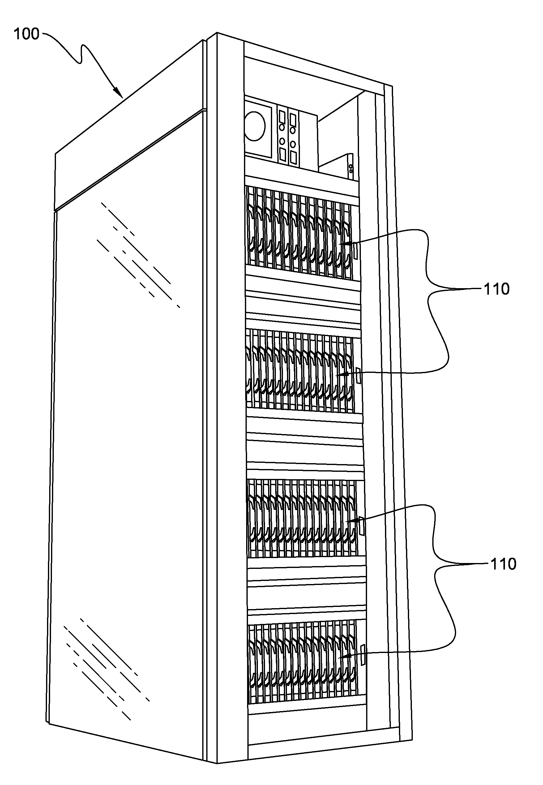
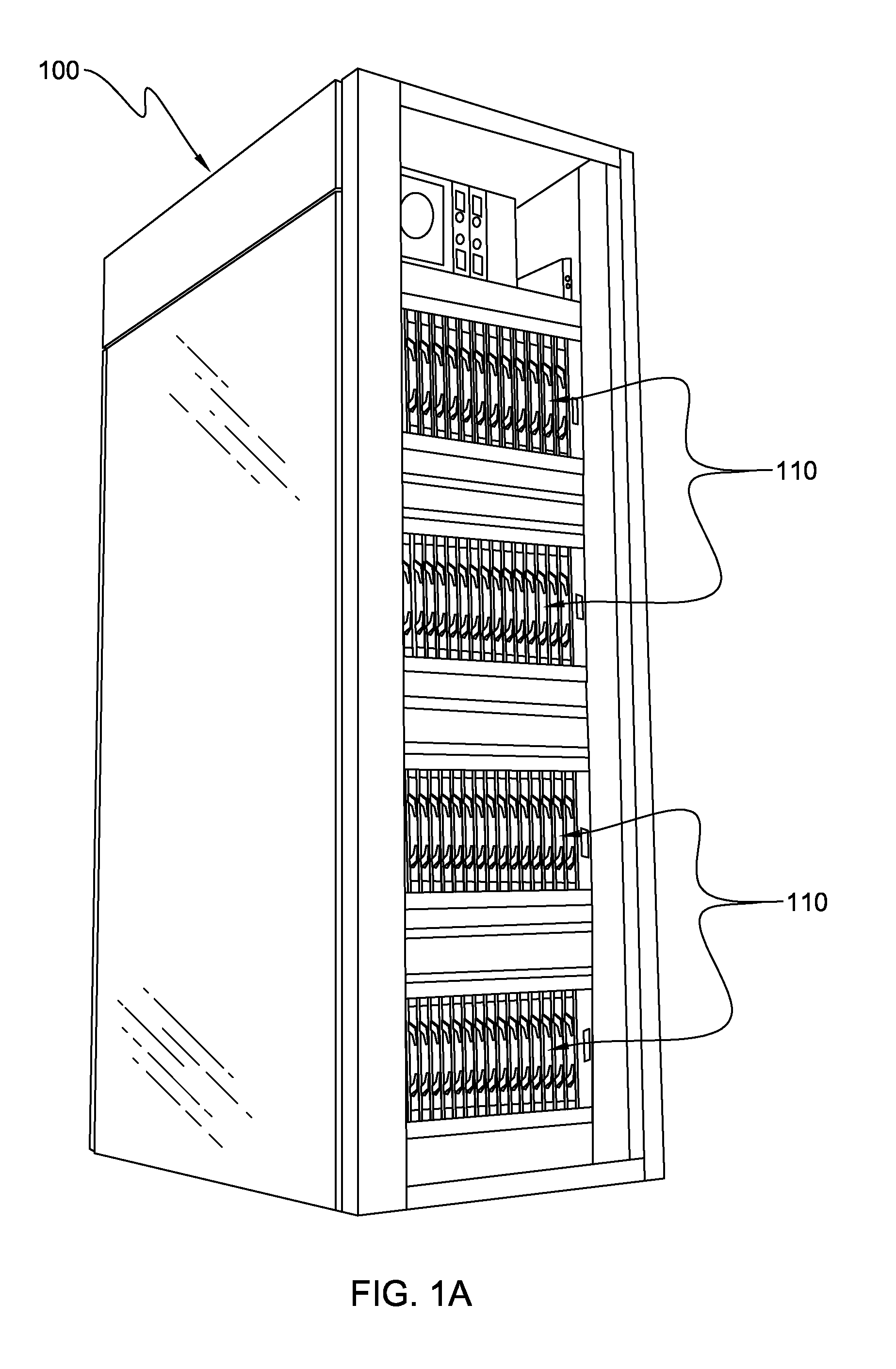
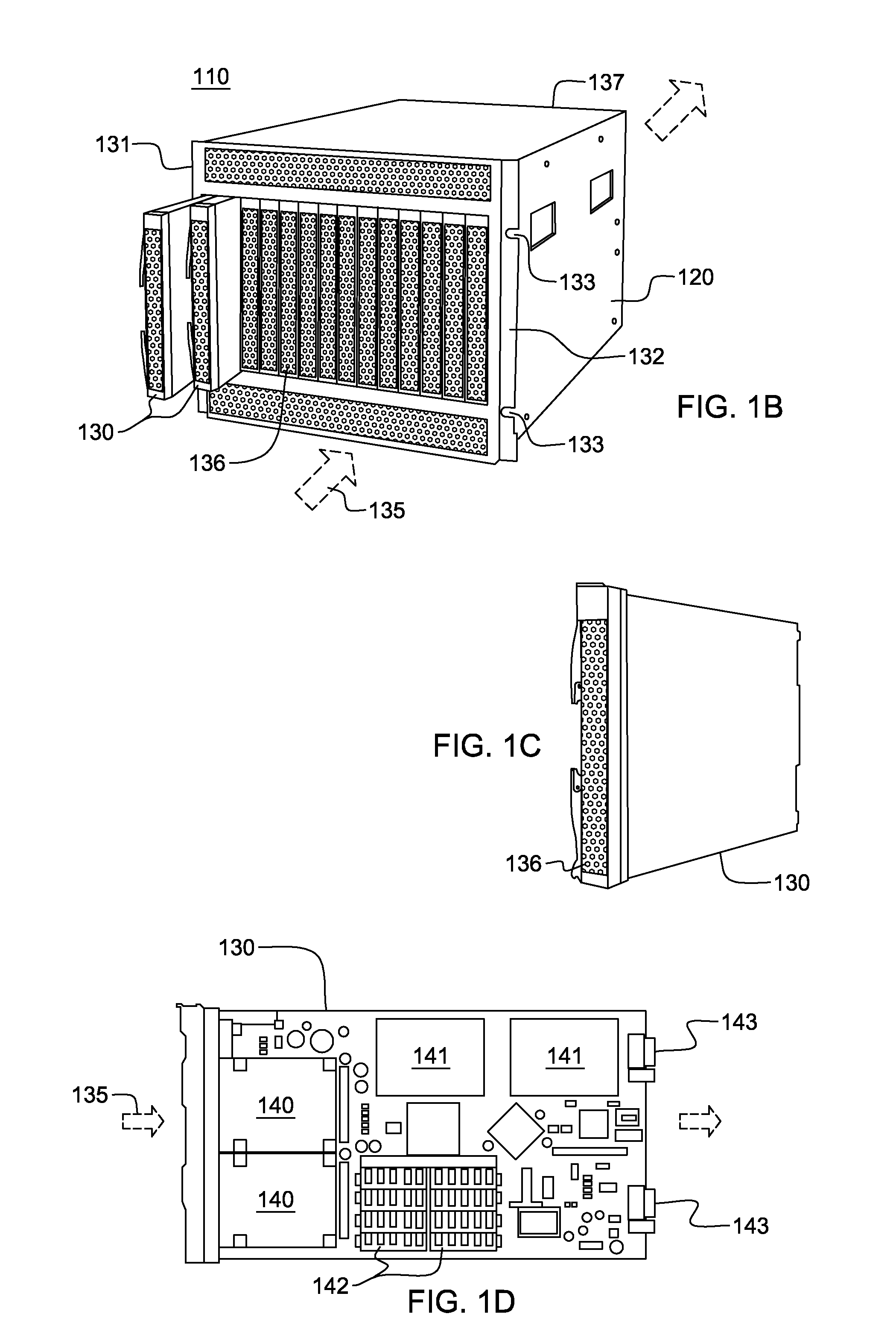
[0025]As used herein, the term “electronics rack”, includes any housing, frame, rack, compartment, blade server system, etc., having one or more heat generating components of a computer system, and may be, for example, a stand alone computer processor having high, mid or low end processing capability. In one embodiment, an electronics rack may comprise multiple electronics system chassis, each having multiple heat generating components or blades disposed therein requiring cooling. As one example, an electronic system chassis may be a multi-blade center system. The blades of each multi-blade center system may be removable, and comprise multiple components to be liquid-cooled. In one example, one or more blades of a multi-blade center system are immersion-cooled blades. “Immersion-cooled blades” refers to any blade, book, node, etc. having multiple components thereof cooled by immersion within coolant flowing through the blade. One detailed example of an immersion-cooled blade is desc...


PUM


Abstract

Apparatus and method are provided for facilitating liquid cooling of a plurality of blades of an electronic system chassis. The apparatus includes a chassis-level manifold assembly with a first coolant path and a plurality of second coolant paths. The first coolant path is isolated from the plurality of second coolant paths by a heat exchanger. The heat exchanger facilitates transfer of heat from coolant within the second coolant paths to coolant within the first coolant path. Each second coolant path is isolated from the other second coolant paths, and coolant passing therethrough facilitates cooling of a respective blade. When operational, each second coolant path forms a portion of a respective closed loop coolant path extending between the manifold assembly and the electronic system chassis, and in one embodiment, each blade is an immersion-blade, with multiple components thereof immersion-cooled by coolant flowing through the respective second coolant path.

Description

TECHNICAL FIELD[0001]The present invention relates to apparatuses and methods for facilitating cooling of an electronics system, such as a multi-blade center system, and more particularly, to apparatuses and methods for facilitating liquid-cooling of the blade units of one or more electronic system chassis.BACKGROUND OF THE INVENTION[0002]The power dissipation of integrated circuit chips, and the modules containing the chips, continues to increase in order to achieve increases in processor performance. This trend poses a cooling challenge at both the module and system level. Increased air flow rates are needed to effectively cool high power modules and to limit the temperature of air that is exhausted into the computer center.[0003]In many server applications, processors along with their associated electronics (e.g., memory, disc drives, power supplies, etc.) are packaged in removable drawer or blade configurations disposed within a housing. Typically, the components are cooled by a...

Claims


Application Information

Patent Timeline
IPC IPC(8): F28D15/00F28F9/22H05K7/20
CPCH05K7/20809G06F1/20H05K7/20
Inventor CAMPBELL, LEVI A.CHU, RICHARD C.ELLSWORTH, JR., MICHAEL J.IYENGAR, MADHUSUDAN K.SIMONS, ROBERT E.
Owner BRAINSCOPE SPV LLC
Why Eureka
Try Eureka