Jumbo hammer clutch impact wrench

a clutch and hammer technology, applied in the direction of percussive tools, manufacturing tools, portable drilling machines, etc., can solve the problems of damage to impact drive components, unnecessarily pushing the hammer, and completely missing the anvils

Active Publication Date: 2010-04-29
VESSEL FUKUCHIYAMA
View PDF17 Cites 18 Cited by
  • Summary
  • Abstract
  • Description
  • Claims
  • Application Information

AI Technical Summary

Benefits of technology

[0023]It is envisioned that the wrench of the present invention can operate at relatively high pressures thus producing relatively high rotational speeds with the motor shaft of the motor. It is therefore a benefit of this wrench 10 that the impact drive 20 is capable of handling high pressures without a speed reducing mechanism or excessively wearing components.

Problems solved by technology

Therefore, when the output shaft is unable to turn the fastener, the cam ball repeatedly pushes the impact clutch and hammers axially forward.
This action often occurs so rapidly that the hammers impact the anvils before corresponding surfaces are fully aligned, or alternatively the hammers completely miss the anvils and fail to produce any additional torque.
Moreover, when the frictional resistance of the fastener exceeds the additional torque produced by the hammers, the cam ball and impact clutch may unnecessarily push the hammers into repeated alignment with the anvils before an operator disengages the motor.
This repeated impact and movement can damage components of the impact drive (e.g., the cam ball and impact clutch) or prematurely wear them out.
Although the components of the impact drive are less prone to damage and wear, the speed reducing mechanism requires the use of additional components adding complexity to the tool.

Method used


Image

  • Jumbo hammer clutch impact wrench
  • Jumbo hammer clutch impact wrench
  • Jumbo hammer clutch impact wrench

Examples


Embodiment Construction

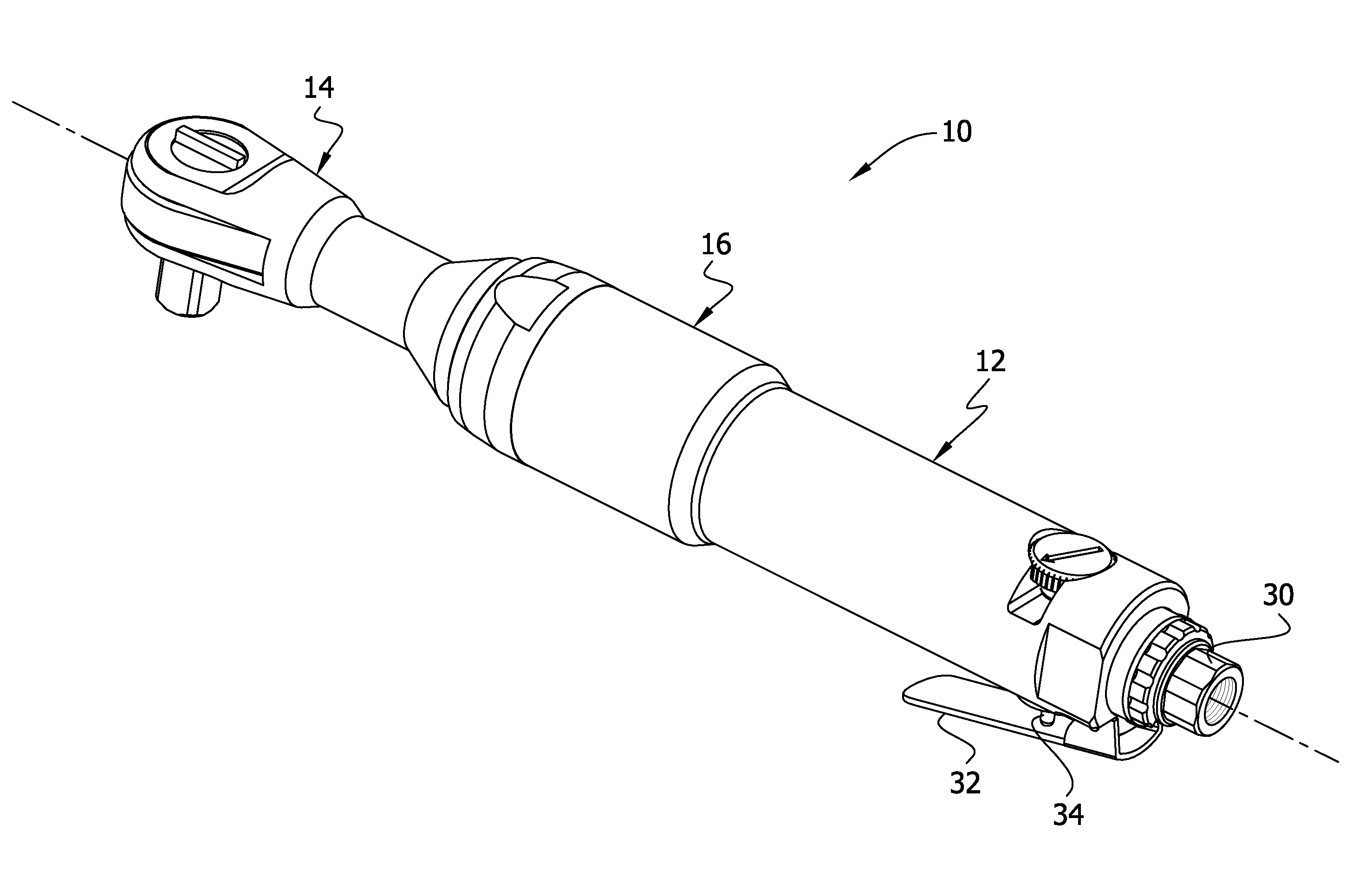
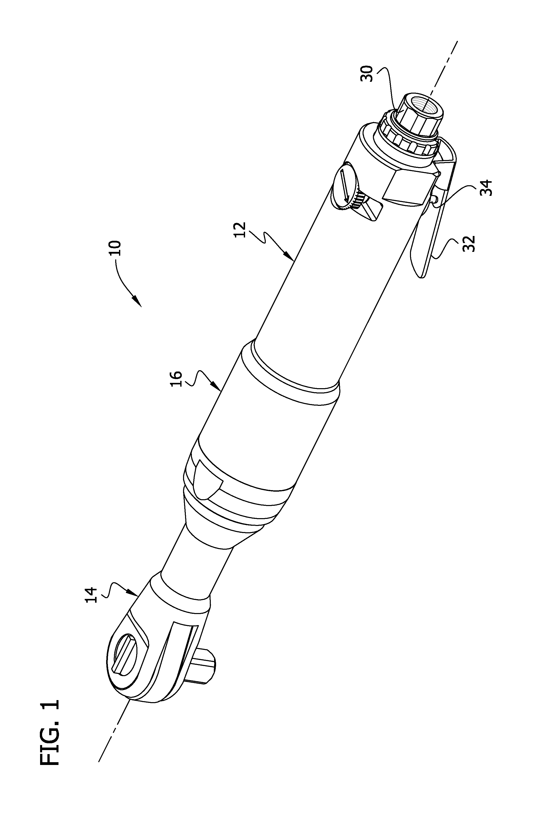
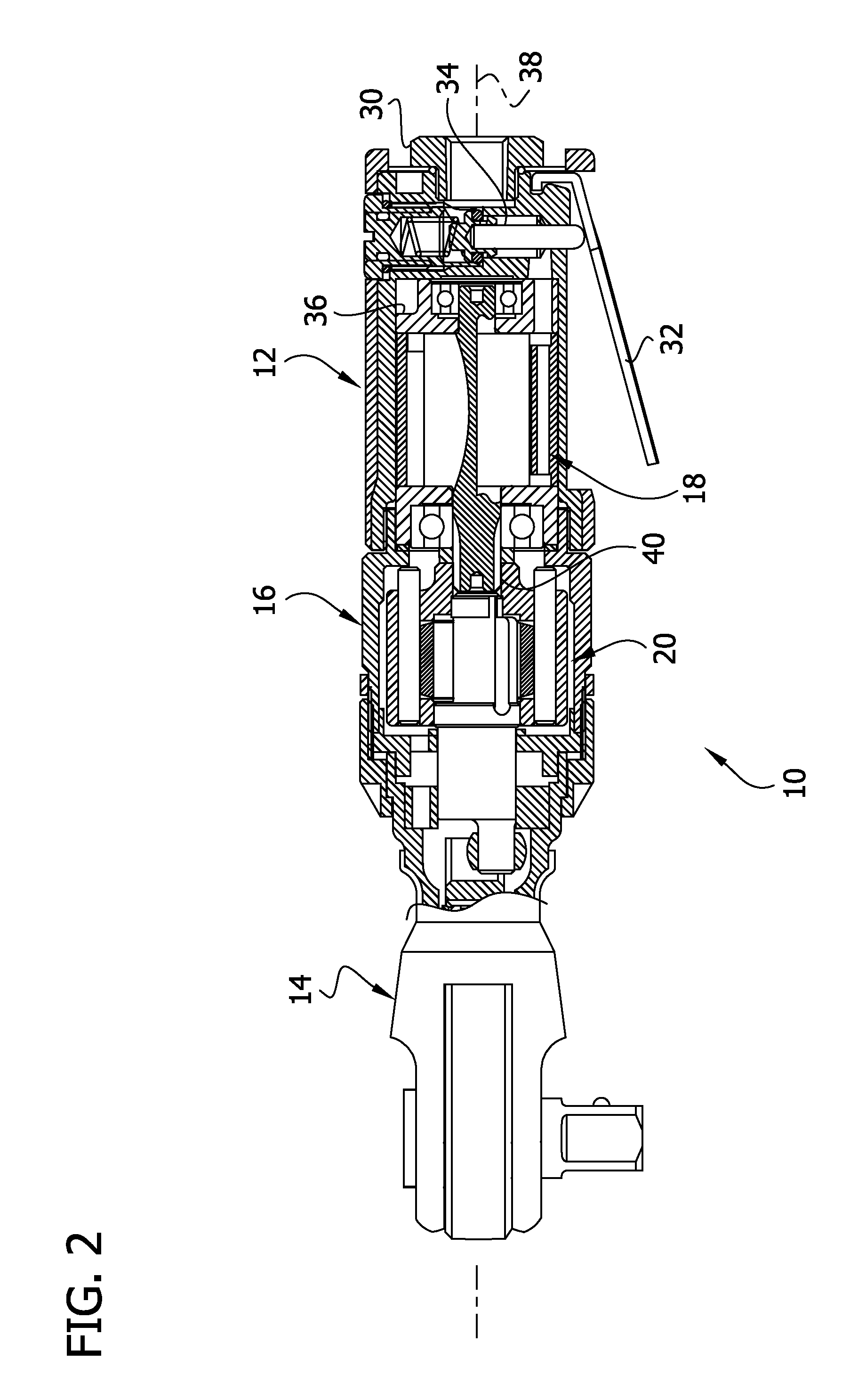
[0018]Referring now to the drawings, and particularly to FIGS. 1 and 2, a hand-held, pneumatically-driven, ratchet wrench is generally indicated at reference numeral 10. The wrench 10 includes a tubular grip, indicated generally at 12, and a head, indicated generally at 14. As shown in FIG. 2, the grip 12 and head 14 are connected by a tubular threaded coupling, generally indicated at 16, so the grip, coupling and head form a housing that houses the functional components of the wrench 10. The grip 12 houses a motor, which is generally indicated at 18. The coupling 16 houses an impact drive, generally designated by 20 and the head 14 houses a ratchet mechanism, generally designated by 22 (FIG. 3). Each of these components will be described in greater detail below. For convenience of description, when describing orientations of components, a forward end of the wrench 10 will be understood to be at an end having the head 14 and a rearward end will be understood to be at an end having t...


PUM

PropertyMeasurementUnit
rotationaaaaaaaaaa
torqueaaaaaaaaaa
frictional resistanceaaaaaaaaaa

Abstract

A power driven tool for rotating a mechanical element. The tool includes a housing and motor. The motor has an output shaft. The shaft rotates relative to the housing. The tool also includes an impact drive axially fixed within the housing. The impact drive includes a base and an anvil shaft having an anvil. The impact drive includes an annular hammer having opposite impact lands pivotally mounted on the base for movement between three positions, including a forward position in which the hammer is positioned so one impact land engages the anvil, a reverse position in which the hammer is positioned so another of the impact lands engages the anvil, and a disengaged position in which neither of the impact lands engages the anvil. Further, the tool includes a ratchet mechanism. The ratchet mechanism includes an output drive mounted for rotation relative to the housing for rotating a mechanical element.

Description

CROSS-REFERENCE TO RELATED APPLICATION[0001]Priority is claimed from U.S. Provisional Patent Application Ser. No. 61 / 108,756 filed Oct. 27, 2008, which is hereby incorporated by reference.BACKGROUND OF THE INVENTION[0002]This invention relates generally to power driven tools, and more specifically to a power driven tool for tightening or loosening fasteners including an impact drive having an oversized hammer clutch.[0003]Power driven tools for tightening or loosening fasteners (e.g., nuts and bolts) are known, and power driven tools incorporating impact drives that can intermittently provide increased torque for tightening or loosening fasteners are common.[0004]An impact wrench incorporating a ratchet head is disclosed in co-owned U.S. Pat. No. 4,821,611, which is incorporated by reference. A pneumatic motor rotates a clutch case that coaxially houses an impact drive. Under normal operation, a cam ball in the clutch case engages a finger of an impact clutch and rotates the clutch ...

Claims


Application Information

Patent Timeline
Patent Type & Authority Applications(United States)
IPC IPC(8): B25B21/02B25B13/46
CPCB25B21/004B25B13/465
Inventor KOBAYASHI, SHIGEKI
Owner VESSEL FUKUCHIYAMA
Why Eureka
Try Eureka