Container for Transporting Piece Goods, Particularly Pieces of Luggage

a technology for luggage and containers, applied in the direction of transportation and packaging, conveyor parts, packaging, etc., can solve the problems of high cost, complex so-called active loading aids of the described type, and the use of drive mechanics, etc., to achieve simple and low-cost design, simple loading and unloading of containers, and high rotation speed

Inactive Publication Date: 2010-04-29
SIEMENS AG
View PDF9 Cites 12 Cited by
  • Summary
  • Abstract
  • Description
  • Claims
  • Application Information

AI Technical Summary

Benefits of technology

[0028]The relative motion of the toothed belts one to another can also of course set in when the container is stationary and the fixed toothed belt is driven, so that the toothed belt of the container is likewise set in motion. The carrying belt can also, as it were, be set in motion during the travel motion of the container, provided that the relative speed to the fixed toothed belt is appropriately chosen. If the fixed toothed belt is driven at a higher speed than the pass-through speed of the container, then the relatively high rotation speed is transmitted to the toothed belt of the container, with the result that the carrying belt is set in motion.
[0029]The two solutions of the invention allow a simple loading and unloading of the containers, both during passage or in a stationary state in the loading and / or unloading station by the drive means which are provided there. The containers themselves are not provided with an active drive, but get their drive energy transmitted in the corresponding station from the drive which is provided there. The containers can hence be of relatively simple and low-cost design, without losing the functionality of known crossover conveyors.

Problems solved by technology

The so-called active loading aid of the described type is very complex and, because of the drive mechanics which are used, also very expensive.
Drawbacks with these systems are the loading and, in particular, unloading devices, which are necessary to tip the piece goods out of the normally gently recessed trays.
This type of conveying technology, as a result of the dependency of the individual vehicles upon the laid conveying section, is very limited in its use and cannot be used, for example, in large airport systems involving large distances.
Moreover, the individual cars are usually provided with drives, which increase the overall complexity of such a system.

Method used


Image

  • Container for Transporting Piece Goods, Particularly Pieces of Luggage
  • Container for Transporting Piece Goods, Particularly Pieces of Luggage
  • Container for Transporting Piece Goods, Particularly Pieces of Luggage

Examples


Embodiment Construction

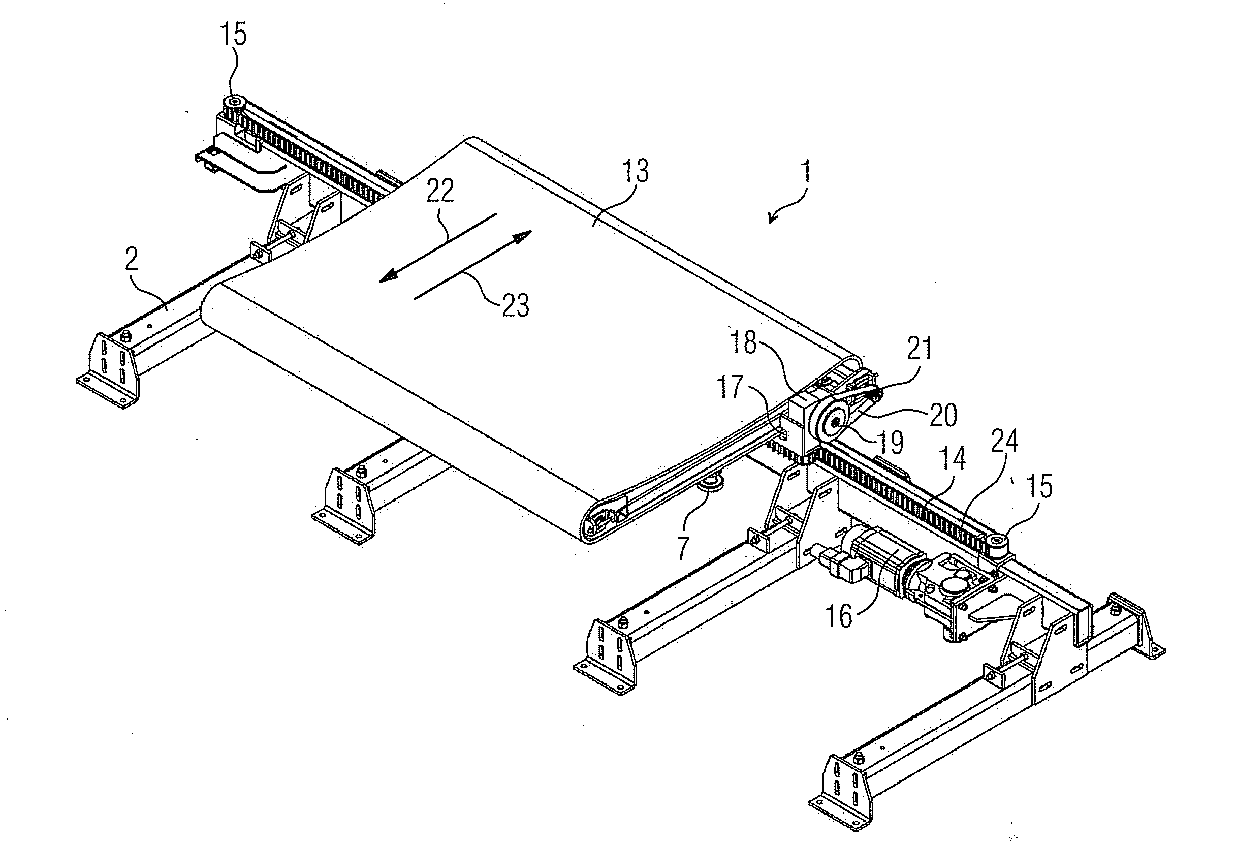
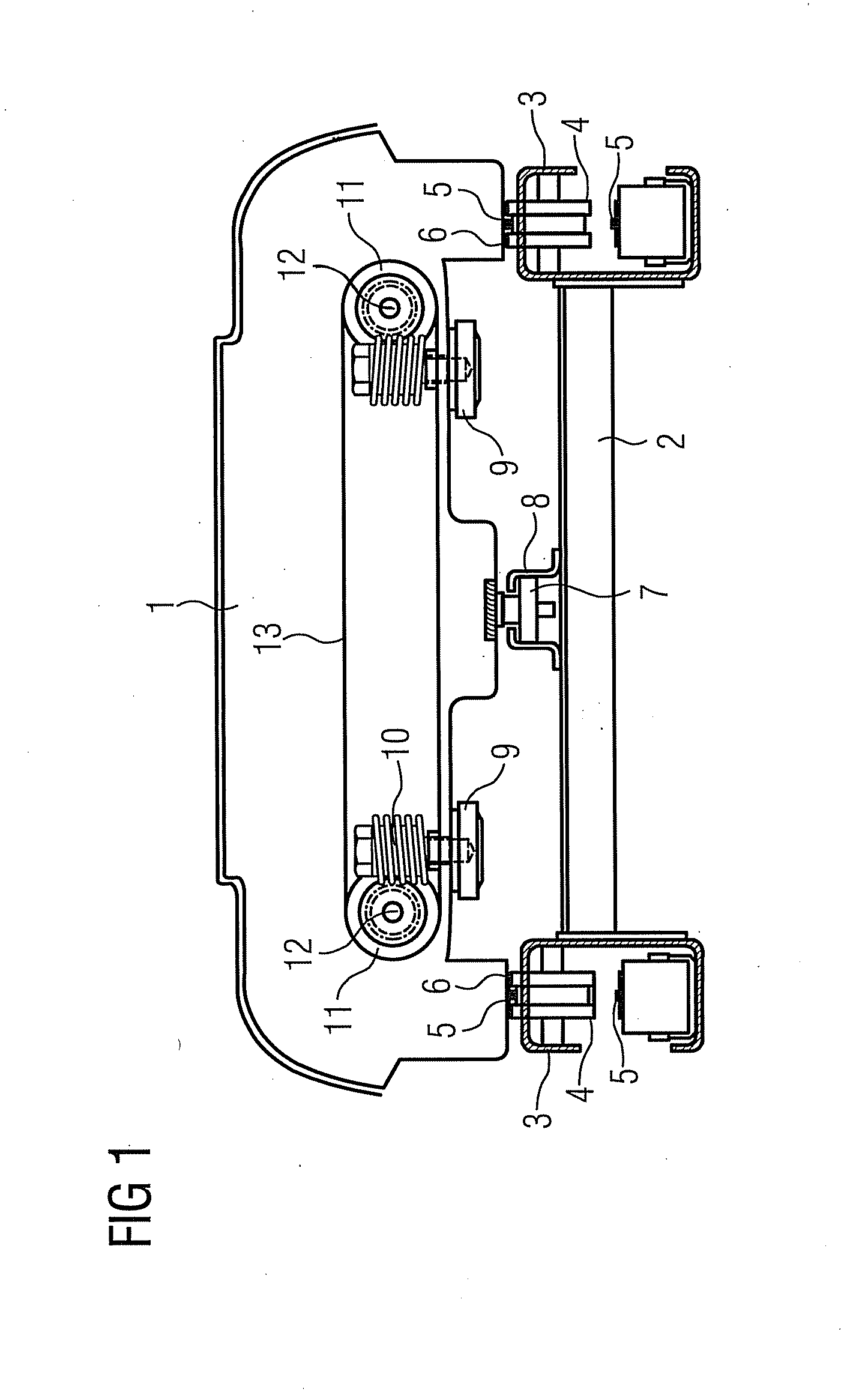
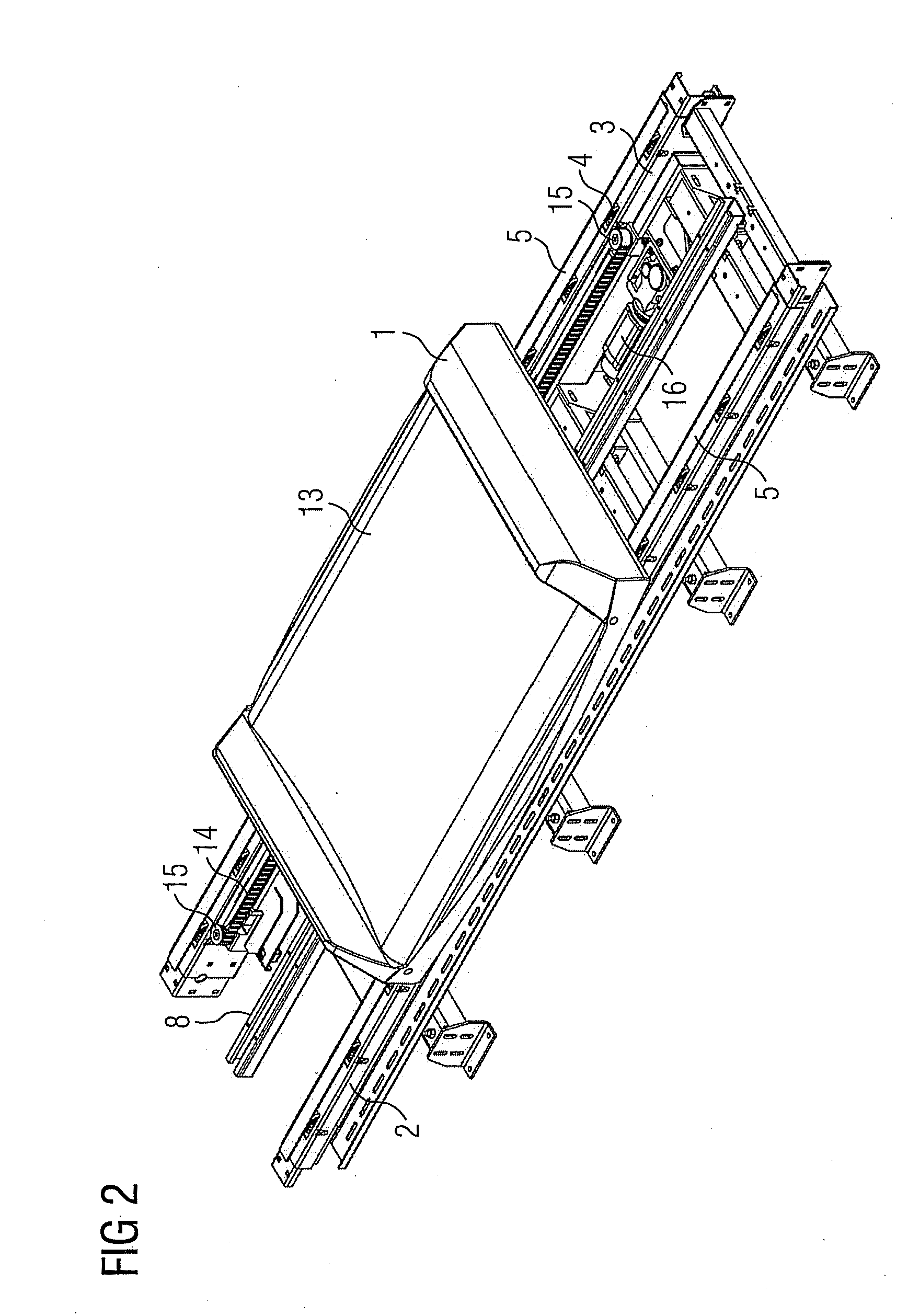
[0034]In FIG. 1, a container according to the invention is denoted by 1, which container is transported on the conveyor track 2. The conveyor track 2 consists of a frame having longitudinal spars 3, in which supporting rollers 4 for two parallel running carrying belts 5 are mounted. The carrying belts 5 are configured as endlessly rotating toothed belts, on whose flat rear sides the container 1 is seated at 6 and is moved via the driven toothed belt 5 in the direction of transport of the conveying system. The container 1 is provided in its longitudinal middle with a perpendicularly downward projecting guide roller 7, which is guided in a guide rail 8 disposed on the frame of the conveyor 2. The container 6 is provided on both sides of its container middle with friction wheels 9, which are fastened in a freely projecting manner on the worm shaft 10. While the friction wheel 9 juts out over the underside of the container 1, the worm shaft 10 projects in the region of the worm wheel 11...


PUM


Abstract

A loading and unloading station for a container that transports piece goods, particularly pieces of luggage on a conveyor belt is provided. The upper part of the container receiving the piece goods is formed by a storage surface for the piece goods, the surface including an continuous carrying belt spanning the lower part of the container and capable of bearing a load, the carrying belt is arranged transversely to the transport direction of the container and drivably guided around a plurality of deflection rollers provided on both sides of the container. A method for transporting piece goods on a conveyor track including supporting and guide elements for the container is also provided.

Description

CROSS REFERENCE TO RELATED APPLICATIONS[0001]This application is the US National Stage of International Application No. PCT / EP2008 / 052725, filed Mar. 6, 2008 and claims the benefit thereof The International Application claims the benefits of German application No. 10 2007 015 307.6 DE filed Mar. 27, 2007, both of the applications are incorporated by reference herein in their entirety.FIELD OF INVENTION[0002]The invention relates to a container for transporting piece goods, particularly pieces of luggage, on a conveyor track having supporting and guide elements for the container and having at least one unloading station for emptying the piece goods out of the container and / or at least one loading station for loading the container with the piece goods, wherein each container consists of an upper part, which receives the piece goods lying thereon, and a lower part resting on the conveyor track.BACKGROUND OF INVENTION[0003]In order to transport piece goods of choice, in particular items...

Claims


Application Information

Patent Timeline
Patent Type & Authority Applications(United States)
IPC IPC(8): B65G47/46
CPCB65G17/345B65G2207/46B65G2207/18
Inventor BAUM, INGOLFBRUTT, JORNHIMMEL, THOMASHUG, JURGENKUBIK, JARO
Owner SIEMENS AG
Why Eureka
Try Eureka