Pulverized material producing system

a technology of producing system and raw material, which is applied in the direction of gas current separation, solid separation, grain milling, etc., can solve the problems of increasing the size of the device, limiting the use of difficult to use raw materials with a higher moisture content, etc., to achieve rapid evaporation of the moisture contained in the raw material, improve energy efficiency, and reliably and efficiently dry raw materials

Inactive Publication Date: 2010-04-29
EARTHLINK
View PDF6 Cites 15 Cited by
  • Summary
  • Abstract
  • Description
  • Claims
  • Application Information

AI Technical Summary

Benefits of technology

[0008]However, because pneumatic conveying driers dry raw materials by causing those materials to pass through the interior of the pneumatic conveying drier itself along with heated air, it is necessary for the overall length of the drier to be long so that raw materials with a high moisture content can be dried sufficiently. Thus, employing such a system increases the size of the device, which in turn leads to a rise in production costs.
[0009]It is an object of the present invention to solve the above-mentioned problems by providing a pulverized material producing system capable of producing a pulverized material having a sufficiently dried raw material, while at the same time suppressing production costs, even in the case where a material having a high moisture content and viscosity is used as the raw material.
[0011]As described above, the pulverized material producing system of the present invention is provided with a circuit, and a raw material is circulated through this circuit by the airflow created by the pulverizer and the air (heated air) from the heated air supplier. At this time, the surface area of the raw material, which has been pulverized many times, increases, and thus the evaporation of the moisture contained in the raw material is promoted quickly. The pulverized material producing system of the present invention therefore is capable of reliably and efficiently drying a raw material even in the case where that raw material has a high moisture content. Furthermore, at this time, the heated air used for drying is circulated through the circuit; therefore, the pulverized material producing system of the present invention provides improved energy efficiency, and thus also can realize a reduction in production costs.

Problems solved by technology

However, even if a pulverized material is to be produced according to the system disclosed in Patent Document 1, the pulverizing process is carried out prior to the drying process, and thus there is a limit to the moisture content of the raw material to be used.
With the system disclosed in Patent Document 1, there is no problem when the raw material used is rice with a moisture content of 28% to 34%, but it is difficult to use materials with a moisture content higher than that, such as raw fish, seaweed, bean curd refuse, and vegetables, as the raw material.
Thus, employing such a system increases the size of the device, which in turn leads to a rise in production costs.

Method used


Image

  • Pulverized material producing system
  • Pulverized material producing system
  • Pulverized material producing system

Examples


embodiment 1

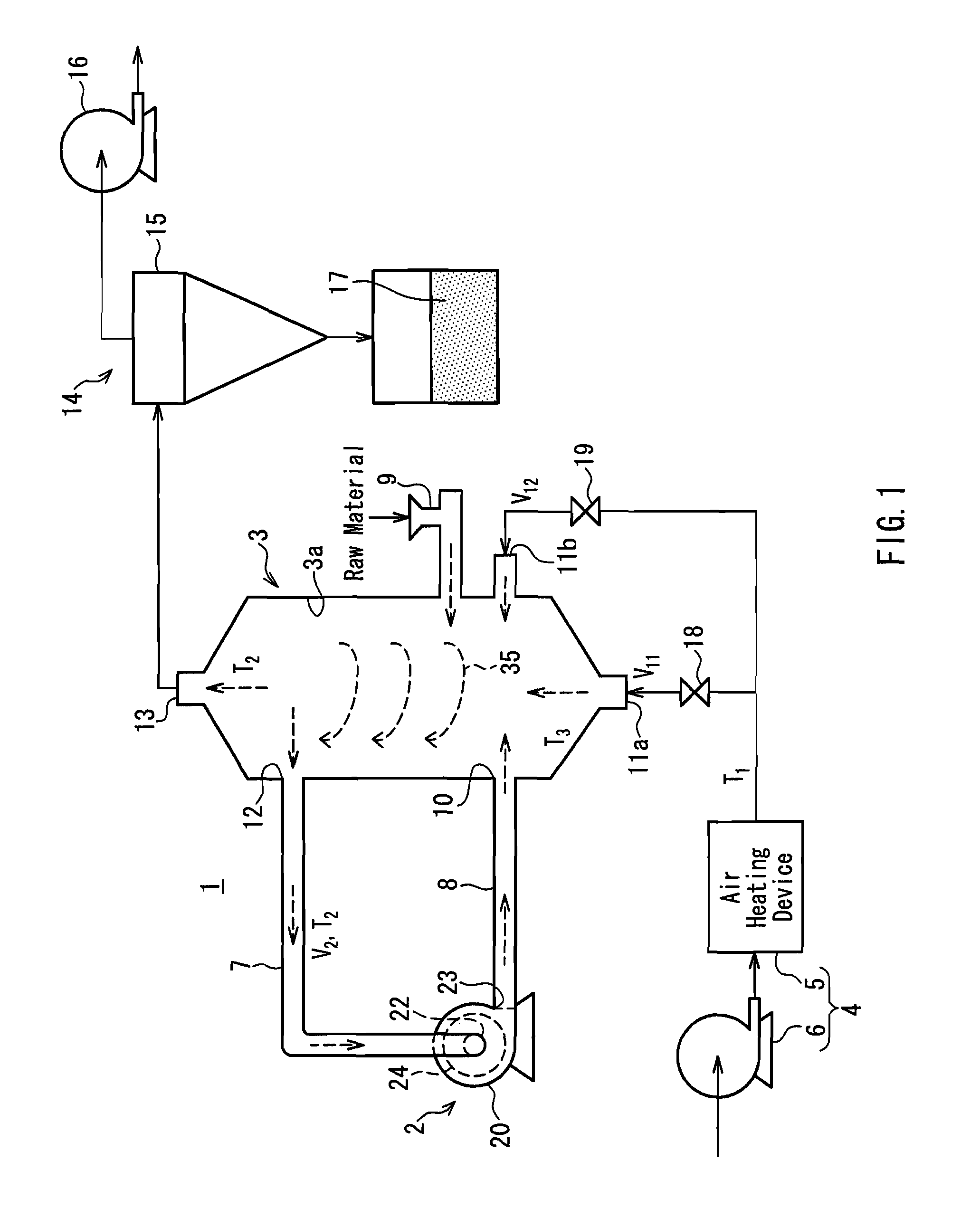
[0117]Hereinafter, a pulverized material producing system according to Embodiment 1 of the present invention shall be described with reference to FIGS. 1 through 6. First, the overall configuration of the pulverized material producing system according to Embodiment 1 shall be described using FIG. 1. FIG. 1 is a structural diagram schematically illustrating the overall configuration of a pulverized material producing system according to Embodiment 1 of the present invention.

[0118]As shown in FIG. 1, a pulverized material producing system 1 includes a pulverizer 2 that pulverizes a raw material, a container 3, and a heated air supplier 4 that supplies air that has been heated (heated air) to the interior of the container 3. The container 3 includes a first inlet 10, second inlets 11a and lib, a first outlet 12, and a second outlet 13. These inlets and outlets all communicate with the interior of the container 3. The heated air supplier 4 supplies heated air for drying the raw material...

embodiment 2

[0163]Hereinafter, a pulverized material producing system according to Embodiment 2 of the present invention shall be described with reference to FIGS. 7 through 12. First, the overall configuration of the pulverized material producing system according to Embodiment 2 shall be described using FIG. 7. FIG. 7 is a structural diagram schematically illustrating the overall configuration of a pulverized material producing system according to Embodiment 2 of the present invention.

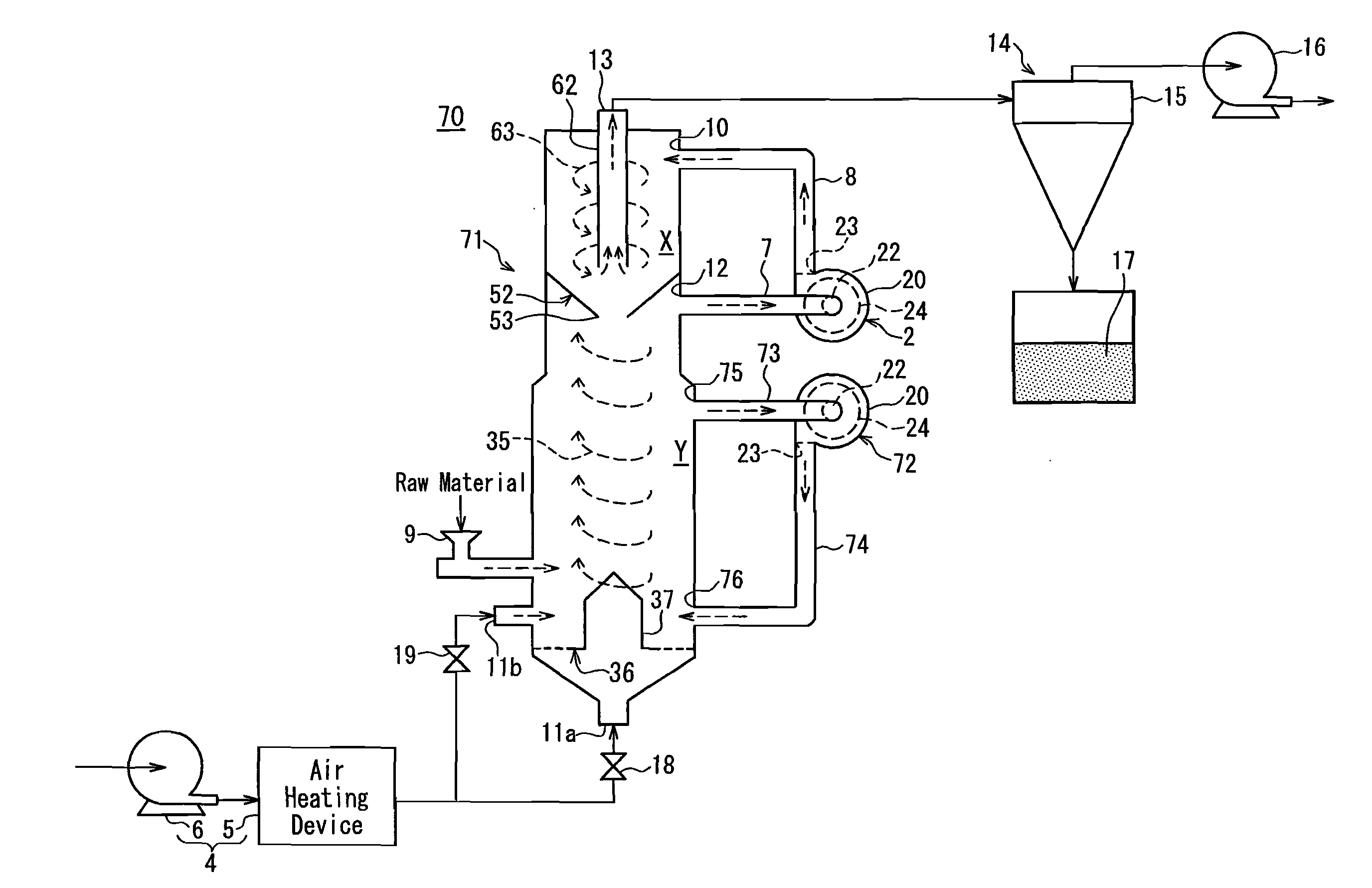
[0164]As shown in FIG. 7, in Embodiment 2, a pulverized material producing system 50 differs from the pulverized material producing system of Embodiment 1 in terms of the structure of a container 40. Aside from that, however, the pulverized material producing system 50 of Embodiment 2 has the same configuration as the pulverized material producing system 1 of Embodiment 1.

[0165]The container 40 has, like the container 3 shown in FIGS. 1 and 3, a cylindrical shape whose cross-section is circular. The container 40 ...

embodiment 3

[0183]Hereinafter, a pulverized material producing system according to Embodiment 3 of the present invention shall be described with reference to FIGS. 14 and 15. FIG. 14 is a cross-sectional view illustrating the detailed configuration of a container used in the pulverized material producing system according to Embodiment 3 of the present invention. FIG. 15 includes diagrams illustrating a plate member shown in FIG. 14; FIG. 15A is a perspective view, and FIG. b) is a plan view.

[0184]As shown in FIG. 14, the pulverized material producing system of Embodiment 3 differs from the pulverized material producing system of Embodiment 1 in terms of the internal structure of a container 3. Aside from the internal structure of the container 3, however, the pulverized material producing system of Embodiment 3 has the same configuration as the pulverized material producing system of Embodiment 1. Like in Embodiment 1, the container 3 is placed vertically in Embodiment 3. Hereinafter, the diffe...


PUM


Abstract

A pulverized material producing system capable of producing a pulverized material dried sufficiently from a raw material, while at the same time suppressing production costs, even in the case where the raw material has a high moisture content and viscosity, is provided. A pulverized material producing system that includes a pulverizer 2, a container 3, and a heated air supplier 4 that supplies heated air is used. The container 3 includes a first inlet 10, second inlets 11a and 11b, a first outlet 12, and a second outlet 13, and is configured so that a swirl flow 35 is created within the container. The heated air is supplied by the heated air supplier 4 to the interior of the container 3 via the second inlets 11a and 11b. The pulverizer 2 includes a casing 20 provided with a suction port 22 and a discharge port 23, an impeller, and a screen 24 that has many pores, and has blower functionality. The first inlet 10 is connected to the discharge port 23 of the casing via a pipeline 7, and the first outlet 12 is connected to the suction port 22 of the casing via a pipeline 8.

Description

TECHNICAL FIELD[0001]The present invention relates to a pulverized material producing system that produces pulverized materials for food products, medical products, cosmetics, resins, inorganic substances, and so on.BACKGROUND ART[0002]Conventionally, pulverized materials have been used in a variety of areas, such as food products, medical products, cosmetics, and so on. Generally, when producing a pulverized material using a material with a high moisture content and viscosity as the raw material, such as with food products, the raw material first is dried sufficiently using a drier, and the dried raw material then is pulverized using a pulverizer. The reason for this is that if a material with a high moisture content and viscosity is loaded into the pulverizer as-is, the pulverizer will become clogged due to the low flowability caused by the viscosity.[0003]Meanwhile, because the drying process and the pulverizing process are performed separately in batches, it is necessary to perf...

Claims


Application Information

Patent Timeline
Patent Type & Authority Applications(United States)
IPC IPC(8): B02C23/24B02C13/08B02C17/16B02C23/28B02C23/32
CPCB02C13/08B02C23/28B02C17/186B02C17/16B02C23/00
Inventor MAEDA, HIROSHIMAEDA, TAIJI
Owner EARTHLINK
Why Eureka
Try Eureka